
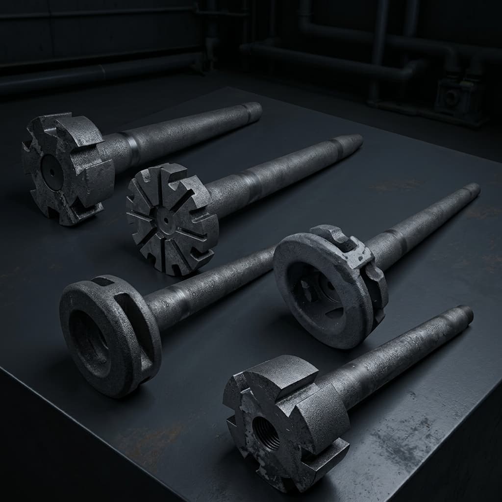
Graphite CNC Machining Design Guide: Tolerances, Threads, and Cost Drivers
Designing custom graphite parts? Read our CNC machining guide covering standard tolerances, threading considerations, wall thickness limits, and tips to reduce your manufacturing costs.
Decision-Level Conclusion: Designing a graphite component is fundamentally different from designing for steel or aluminum. Graphite is brittle, abrasive, and highly notch-sensitive. To minimize manufacturing costs and prevent catastrophic part breakage during high-temperature operation, engineers must maximize radii on internal corners, avoid ultra-fine threads, and specify tolerances only as tight as functionally necessary.
When transitioning a thermal or mechanical prototype into mass production, the way a graphite part is designed directly dictates its unit price. Because graphite CNC machining involves cutting a brittle, ceramic-like material, standard metalworking design rules do not always apply.
Whether you are designing a vacuum furnace hot zone fixture, a semiconductor susceptor, or a continuous casting die, following this engineering design guide will help you optimize your CAD drawings for manufacturability, extend the lifespan of your parts, and aggressively reduce your procurement costs.
1. Standard Machining Tolerances vs. Precision Costs
Graphite is dimensionally exceptionally stable. It does not suffer from the residual stress warping commonly seen in metals (like aluminum or stainless steel) when large amounts of material are removed. However, its granular, brittle nature means holding microscopic tolerances can be difficult and expensive due to microscopic edge chipping during the milling process.
- Standard Commercial Tolerance (Cost-Effective): ± 0.05 mm (± 0.002"). This is easily achievable on standard graphite CNC routers and does not incur any cost premiums.
- Precision Tolerance (Premium Cost): ± 0.01 mm to ± 0.02 mm. Achievable only on high-end VMCs using premium isostatic graphite with ultra-fine grain sizes. Expect a cost premium because the machinist must manage rapid tool wear (graphite is highly abrasive to carbide tools) and use significantly slower feed rates.
- DFM Tip: Do not blanket-tolerance your entire drawing to ± 0.01 mm. Only apply tight tolerances to critical mating surfaces (e.g., press-fit pins or sealing faces). Leave non-critical outer dimensions at ± 0.10 mm to save money.
2. Corner Radii and Fillets (The Golden Rule of Graphite)
Graphite is highly notch-sensitive. A sharp internal corner acts as a massive stress riser. When subjected to mechanical load (tightening a bolt) or thermal shock (rapid heating in a furnace), a graphite part will almost always fracture originating from a sharp internal corner.
Internal Corners
- Never design a sharp 90-degree internal corner unless it is absolutely functionally unavoidable.
- Always specify the largest internal radius (fillet) your design can tolerate. A minimum radius of R1.0 mm (R0.040") is recommended, but R3.0 mm or larger is heavily preferred for structural integrity.
- Machinability: CNC endmills are round. Machining a perfectly sharp internal corner requires secondary operations (like broaching or EDM sinking into the graphite), which drastically increases costs.
External Edges
- Sharp external edges are incredibly prone to chipping during handling, shipping, and final assembly.
- Always specify a minimum 0.5 mm x 45° chamfer or R0.5 mm radius on all external edges to prevent breakout and guarantee safe handling by operators.
3. Wall Thickness Limits and Deflection
Because graphite lacks the tensile strength and ductility of metal, ultra-thin walls are prone to shattering from the high-frequency vibration of the cutting tool during milling.
- Standard Minimum Wall Thickness: For most structural furnace components, aim for a minimum wall thickness of 3.0 mm (0.120").
- Extreme Precision Limits: For very small, precise parts (using high-strength isostatic graphite, such as semiconductor ion implant components), walls can be machined down to 0.5 mm (0.020"). However, yield rates will drop, feeds must be slowed to a crawl, and packing/shipping becomes highly specialized.
4. Threads and Tapping: How to Prevent Pull-Out
Threading graphite is common, especially for furnace heating element connectors and fastening graphite plates together. However, graphite threads are notoriously weak in shear strength compared to steel.
| Thread Parameter | Bad Design (Will Fail) | Good Design (Highly Reliable) |
|---|---|---|
| Thread Pitch | Fine pitches (e.g., M6x0.5) | Coarse pitches (e.g., M8x1.25, UNC) |
| Thread Profile | Standard 60° V-Thread | ACME, Round (Knuckle), or Trapezoidal |
| Thread Depth | 1x Diameter | Minimum 2.5x to 3x Diameter |
| Clearance | Tight, interference fit | Loose, thermal expansion allowance |
Engineering Rationale: The thin graphite peaks of a fine pitch thread will crumble instantly when torque is applied. Coarse threads provide a thicker base for the thread root. Whenever designing massive furnace electrodes, use round threads or custom trapezoidal threads; the wider root of these profiles significantly improves pull-out strength and prevents the threads from shearing off under heavy loads.
5. Material Grade Selection Impacts Design
Your CAD design is only as good as the raw material block it is cut from. You must align your design intent with the correct graphite manufacturing process.
- For Thin Walls & Mirror Finishes: If your part has very thin walls, intricate features, or requires a smooth finish, you must specify an ultra-fine grain isostatic graphite. Coarse graphite will simply tear.
- For Massive Structural Blocks: If your part is a massive structural block with simple holes and slots, specifying a high-end isostatic grade is a severe waste of money. A quality molded or extruded graphite is entirely sufficient and will reduce your material BOM by up to 60%.
6. Surface Finish (Ra) Expectations
- Standard Machined Finish: Ra 1.6 to Ra 3.2 μm is typical and requires no special effort.
- Smooth Finish: Ra 0.8 μm can be achieved with fine-grain materials and specialized diamond-coated tooling.
- Measurement Note: Because graphite is inherently porous, you cannot measure its surface finish the exact same way you measure steel. A traditional stylus profilometer will drop into the natural surface pores of the material, sometimes giving artificially rough or inconsistent readings. Laser or optical measurement is preferred for critical seal faces.
Partnering for Manufacturability (DFM)
The best way to reduce the cost of your custom graphite parts is to involve your manufacturing partner early in the design phase. At Custom Graphite Parts, our engineers routinely review client CAD models to identify areas where a simple design tweak—like increasing an internal radius, changing a thread pitch, or relaxing a non-critical tolerance—can cut CNC machining time in half and drastically improve the lifespan of the part.
Ready to move from prototype to production with confidence? Submit your STEP files for a free Design for Manufacturability (DFM) review and RFQ today.
Engineering FAQ: CNC Machining Graphite
1. What is the absolute minimum wall thickness for graphite machining?
For standard structural components, 3.0 mm (0.120") is the safe minimum. For ultra-precision applications like semiconductor components using high-strength isostatic graphite, walls can be machined down to 0.5 mm (0.020"), though yield rates will decrease.
2. How do I prevent graphite threads from stripping?
Avoid fine metric or UNC threads. Use coarse pitches (e.g., M8x1.25 minimum), and ideally design custom round (knuckle) or ACME threads. Ensure a minimum thread depth of 2.5x to 3x the diameter.
3. Do I need to use coolant when CNC machining graphite?
No. Graphite is machined dry using high-velocity vacuum systems to evacuate the highly abrasive dust. Using liquid coolant turns graphite dust into an abrasive sludge that will rapidly destroy machine guideways and ballscrews.
4. Which graphite grade should I select for EDM vs. furnace fixtures?
Use isostatic graphite (grain size < 10µm) for EDM electrodes and fine details. Use extruded or molded graphite for massive structural furnace hot zones to reduce material costs by 40-60%.
Author
Graphite CNC machining, EDM electrode, mold tooling, and export-aware sourcing specialists.
Categories
More Posts
Carbon-Carbon (C/C) Composites vs. Isostatic Graphite: Vacuum Furnace Fixture Selection Guide
Compare C/C composites vs isostatic graphite for vacuum furnace fixtures: thermal mass, TCO, risks, checklist, and RFQ guidance from Custom Graphite Parts.
Copper vs. Graphite EDM Electrodes: A Cost and Performance Analysis
Should you use copper or graphite for your EDM electrodes? We break down the differences in machining speed, wear resistance, surface finish, and overall cost to help plastic mold shops make the best choice.
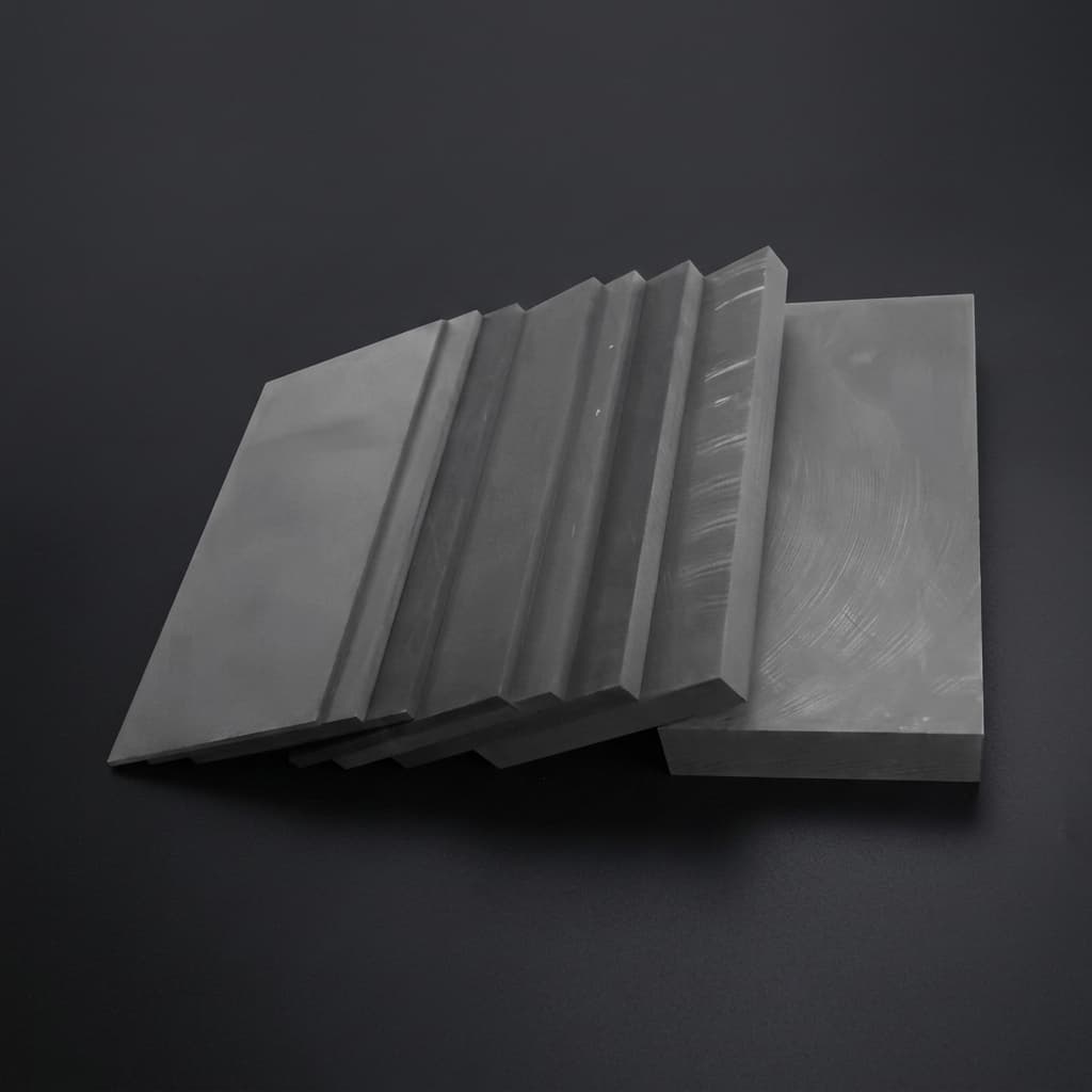
Isostatic vs. Molded Graphite: Which Grade Should You Choose?
An engineering guide comparing isostatic and molded graphite. Learn about grain size, density, strength, and how to select the right graphite grade for EDM, continuous casting, and vacuum furnaces.