
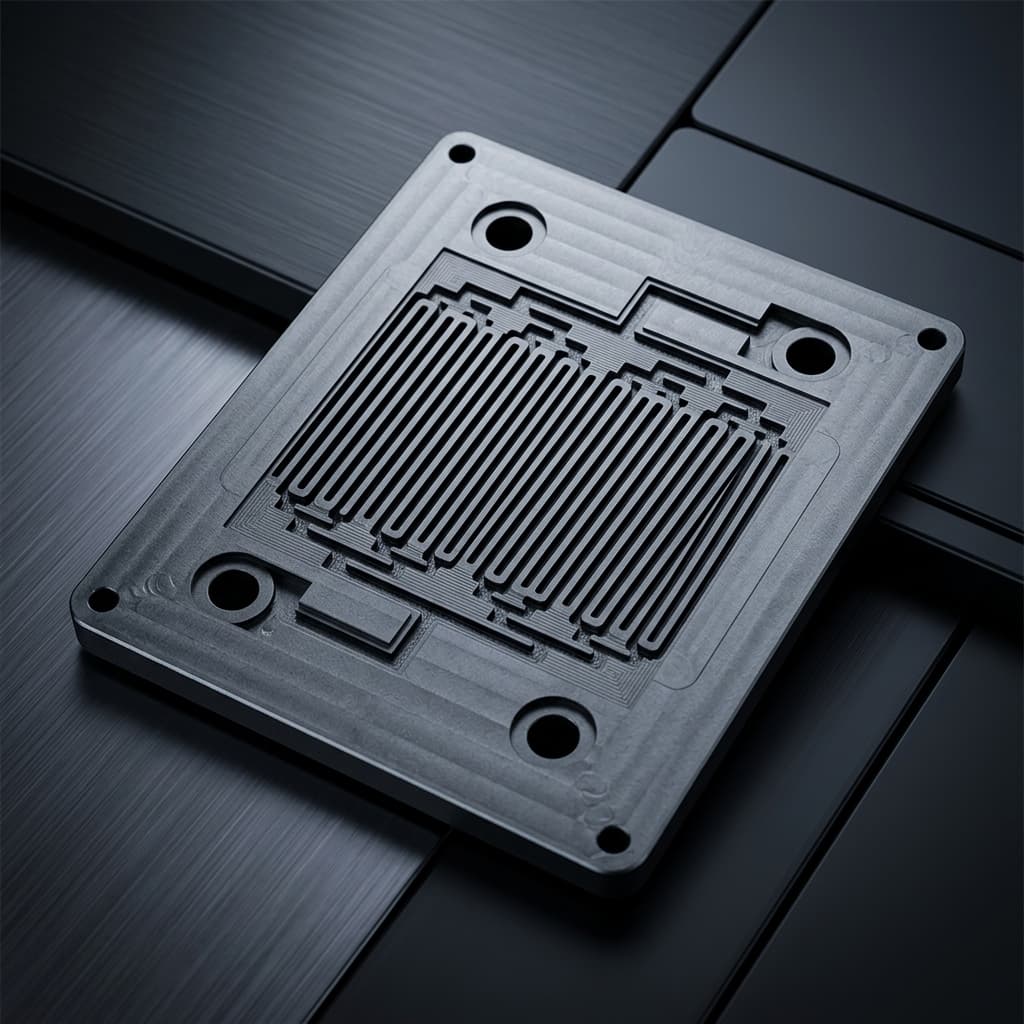
Graphite Bipolar Plates for PEM Fuel Cells and Electrolyzers: CNC Micro-Channel Machining, Resin Impregnation, Gas Permeability & Clamping Tolerances Guide
Specify graphite bipolar plates for PEM fuel cells: compare CNC routes, resin sealing, leak tests and clamping tolerances. Prepare drawings for a DFM review.
Executive Procurement Summary: Graphite bipolar plates can support PEM fuel cell development when electrical contact, gas tightness, and brittle-part handling are qualified together. CNC machining allows flow-field revisions without a production mold, but fixture, programming, inspection, and impregnation costs still apply. First identify the electrochemical duty: a fuel-cell graphite specification does not establish suitability for the oxygen-evolving side of a PEM water electrolyzer. Before release, agree the material and resin, channel geometry, remaining web, leak-test method, and stack compression with the stack designer.
Published: November 1, 2026. Last updated: November 1, 2026. This English-language guide is for stack hardware engineers and technical buyers sourcing globally. It provides a drawing-review and supplier-qualification framework, not a validated stack design or a pressure-safety approval. Units are SI unless otherwise identified.
Evidence and scope: The linked DOE transportation fuel-cell targets are historical development benchmarks, not universal acceptance limits. SGL Carbon's SIGRACELL information describes a particular expanded-graphite/polymer product route, not all machined graphite. A linked PEM electrolysis experiment supports the need for separate oxygen-side material qualification. The calculations below are illustrative drawing checks; no original stack tests, measured production yields, customer results, or lifetime guarantees are claimed.
For rapid prototyping or custom plate manufacturing from 2D/3D CAD models, request a bipolar plate DFM review. You can also review our graphite bipolar plates product catalog and fuel cell and flow battery solutions overview.
1. Stack Working Environment: The Functional Demands on Bipolar Plates
A bipolar plate (BPP) serves four simultaneous roles in a PEM fuel cell stack:
- Current Collection & Electron Conduction: Conducts current between adjacent cells while limiting ohmic voltage drop (
current × resistance). - Reactant Distribution & Gas Separation: Distributes hydrogen and air or oxygen over their respective active areas while maintaining the specified gas-containment barrier.
- Thermal Management: Transfers electrochemical heat to the stack's cooling system; some plate assemblies include internal coolant passages.
- Water and Liquid Product Evacuation: Transports product water away from cathode catalyst layers to prevent flooding while avoiding dry-out in membrane hydration zones.
+-----------------------------------------------------------------------------------+
|                        BIPOLAR PLATE DESIGN TRADEOFF MATRIX                       |
+-----------------------------------------------------------------------------------+
| Higher Resin Loading              --->  Potentially Lower Gas Leakage             |
|                                   --->  Lower Bulk & Interfacial Conductivity     |
| Thinner Plate Profile             --->  Smaller Stack Pitch                       |
|                                   --->  Less Web and Handling Margin             |
| Narrower Rib Lands                --->  Changed Gas Access and Contact Area       |
|                                   --->  Changed GDL Support and Chipping Risk     |
+-----------------------------------------------------------------------------------+
PEM fuel cells and PEM electrolyzers require different material decisions
Specify temperature, media, electrode potential, absolute pressure, and pressure differential separately. A material's resistance to an acid does not establish its resistance to electrochemical oxidation. Carbon corrosion is a concern in oxidizing service; resin impregnation does not qualify graphite for a PEM electrolyzer's oxygen-evolving anode.
For PEM water electrolysis, oxygen-side hardware commonly uses corrosion-resistant metallic systems such as coated titanium. Wakayama and colleagues' Ti₄O₇-coated titanium study illustrates this separate material route. Treat any proposed graphite hydrogen-side component as a separate qualification task, including startup and shutdown conditions. A bipolar plate exposed to the next cell's oxygen side cannot be approved solely on hydrogen-side compatibility.
2. Micro-Channel Flow Field Anatomy: Geometry and Machining Limits
The flow field geometry machined into the plate faces affects reactant pressure drop, distribution over the gas diffusion layer (GDL), and plate structural stiffness.
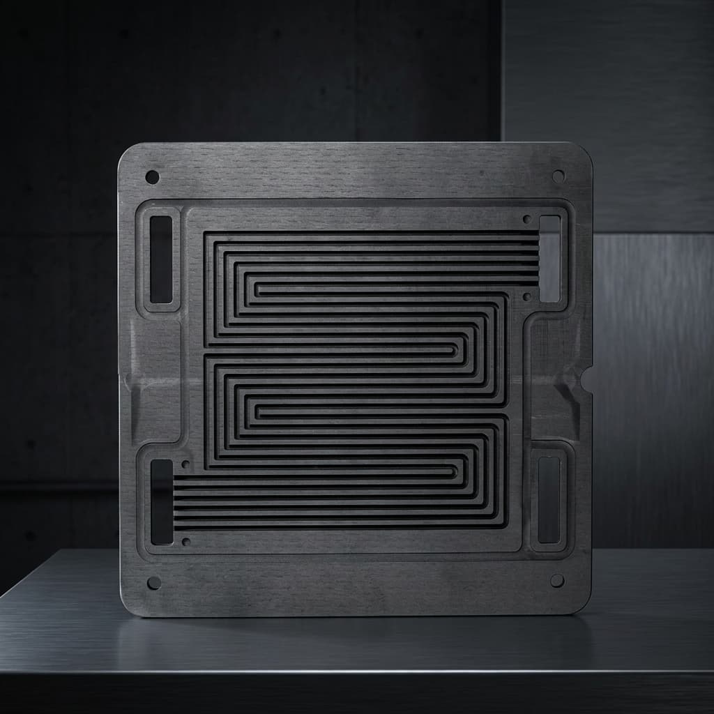
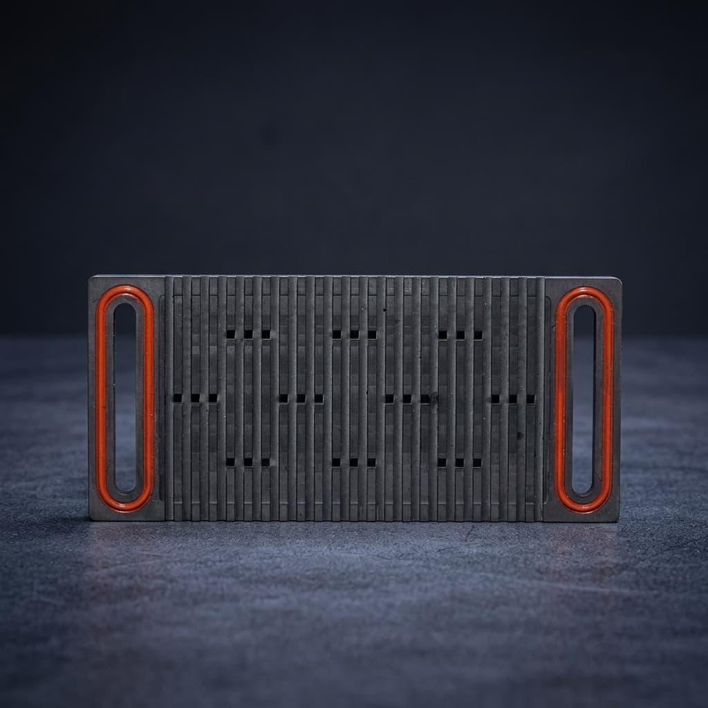
Product illustration from our catalog; the image does not demonstrate a measured leak rate, material grade, or qualified pressure rating.
Key Geometric Parameters
- Channel width (
w_c): The open slot carrying reactants. Evaluate flow resistance and water removal together with the unsupported GDL span; intrusion depends on the chosen GDL and compression. - Rib or land width (
w_r): The contact face supporting the GDL and carrying current and clamping load. Narrow ribs change gas access and contact area but also increase sensitivity to grain pull-out, tool wear, and edge damage. - Channel depth (
d_c): The milled groove depth. Evaluate it with channel width, length, flow rate, and bends; a single depth exponent does not describe every flow field, especially with two-phase flow. - Residual web thickness (
t_w): The solid material remaining between opposing channel floors. Review the actual overlap of channels, ports, and coolant passages on both faces rather than checking nominal plate thickness alone.
A Reproducible Web-Thickness Drawing Check
Illustrative arithmetic, not a tested minimum: Where channels on opposite faces overlap, use t_w = total plate thickness − top channel depth − bottom channel depth.
For a nominal 1.50 mm plate with two 0.60 mm deep channels, the nominal web is 1.50 − 0.60 − 0.60 = 0.30 mm. If the total thickness can be 0.02 mm below nominal and each depth can be 0.015 mm above nominal, the worst-case dimensional web is 1.48 − 0.615 − 0.615 = 0.25 mm. This check assumes the depth datums and thickness measurements describe the same local section; add positional, flatness, and process allowances where applicable.
A simple bending model gives web stress proportional to pressure differential × channel width² / web thickness² for unchanged support geometry. Reducing the web from 0.50 mm to 0.20 mm therefore multiplies the model's stress by (0.50 / 0.20)² = 6.25. This scaling is not a burst-pressure prediction: boundary conditions, local defects, material variability, and load transients still require analysis and component testing.
There is no universal safe web thickness in this guide. If the tolerance stack leaves insufficient margin, discuss thicker stock, shallower channels, revised overlap, or a bonded assembly. A bonded design adds its own joint, seal, and durability qualification requirements.
3. Micro-Channel Cross-Section & Clamping Vectors
The schematic below identifies the interfaces and dimensions to discuss during a PEM fuel-cell plate drawing review. It represents a fuel-cell plate, not an approved PEM electrolyzer oxygen-side construction.
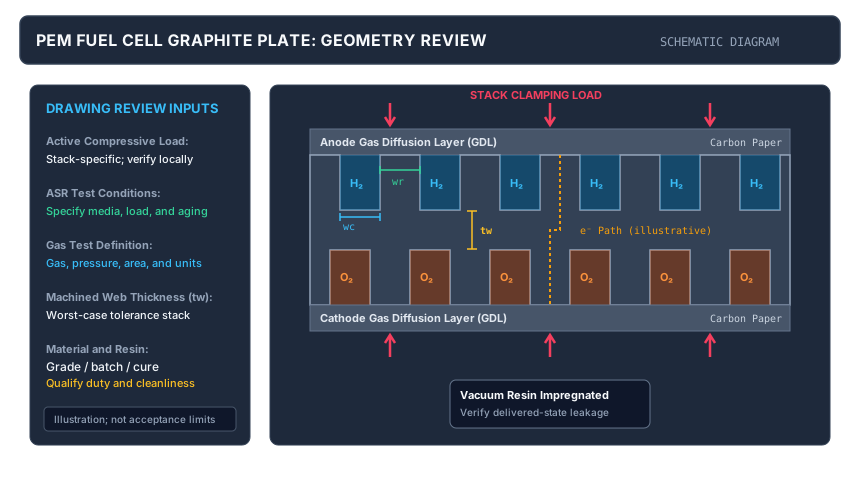
Original explanatory schematic, not to scale. Labels identify clamping load, carbon-paper GDLs, rib width (w_r), channel width (w_c), and residual web (t_w). No numerical acceptance limits or measured performance are implied.
4. Resin Impregnation: Gas Tightness and Cleanliness
Machined synthetic graphite can contain connected open pores. Gas containment therefore requires a qualified material and sealing process, not a density claim alone. Resin impregnation can reduce leakage, but neither the process name nor the description “impermeable graphite” establishes zero gas transport.
Vacuum Pressure Impregnation (VPI) Process
A supplier's qualified process may include these steps; this is a process-review checklist, not an autoclave operating recipe:
- Drying and evacuation: Remove moisture and trapped gas using conditions compatible with the graphite and impregnant.
- Resin introduction: Identify resin chemistry, viscosity, batch, storage history, and compatibility with the actual fluid and temperature.
- Pressure-assisted penetration: Document the validated vacuum/pressure cycle and how pore filling is assessed.
- Surface cleaning and curing: Follow the resin's qualified cure schedule and check for residue, distortion, or cracking. A polymer-rich rib surface can increase contact resistance.
- Final-state verification: Agree whether machining precedes or follows impregnation and which operations can reopen pores. Inspect and leak-test the delivered condition; require requalification after material or process changes.
Gas Permeability Is Not a Helium Leak Rate
The DOE bipolar-plate table lists a 2020 transportation PEM fuel-cell target, not a current universal procurement standard: hydrogen permeation below 1.3 × 10⁻¹⁴ Std cm³/(s·cm²·Pa) at 80°C, 3 atm, and 100% relative humidity. Its separate ASR target is below 0.01 Ω·cm², including contact resistance measured on both sides at 200 psi (about 1.38 MPa), with before/after electrochemical-test conditions in the footnote.
A helium result in mbar·L/s is a gas throughput for a particular test setup. An area-normalized result in mbar·L/(s·cm²) adds another basis. Neither can be substituted directly for the DOE hydrogen metric without the gas, pressure, temperature, specimen, and method definitions. Likewise, a pass at one pressure does not establish a plate's allowable working pressure.
Write the acceptance test explicitly: gas species and purity, test direction, absolute and differential pressures, temperature, conditioning, dwell time, fixture seals, background leakage, calibrated sensitivity, tested area, units, and acceptance limit. Distinguish leakage through the plate from leakage at the fixture or gasket.
Leaching Risks and Catalyst Compatibility
Residual resin constituents or cleaning residues can contaminate the stack. Ask for a material-specific extraction and compatibility plan covering cure verification, extraction medium, exposure time and temperature, blank correction, total organic carbon, conductivity, and relevant ionic or metallic contaminants. The stack designer should set limits based on the MEA and coolant requirements. A TOC or conductivity result alone cannot certify zero catalyst poisoning or lifetime durability.
5. Technical Comparison: Plate Manufacturing Architectures
Choose a process using the same drawing revision and qualification requirements. These are qualitative sourcing trade-offs, not a cross-vendor performance dataset or a price quotation. In particular, SGL Carbon's SIGRACELL page describes expanded-graphite/polymer plates and directional, compression-dependent properties; those claims do not transfer to machined isostatic graphite.
| Evaluation metric | CNC-machined graphite with qualified impregnation | Molded graphite-polymer compound | Expanded-graphite/polymer plate | Coated metallic plate | Procurement decision |
|---|---|---|---|---|---|
| Material identity | Specify graphite grade and impregnant separately | Specify filler, binder, and molding route | Specify graphite structure and polymer route | Specify substrate alloy and coating | Approve the exact material system, not “graphite” alone. |
| Electrical behavior | Check bulk and contact resistance after final processing | Binder and orientation affect conductivity | Direction and compression affect resistance | Contact resistance can be governed by the coating or oxide | Compare through-plane and interfacial results under matching conditions. |
| Gas or liquid barrier | Depends on porosity, impregnation, and final machining | Depends on compound and forming quality | Depends on structure, polymer, and defects | Sheet, welds, ports, and coating require separate checks | Use one agreed test basis; avoid comparing unlike permeability units. |
| Channels and ribs | Revisable by machining; tool access and chipping constrain detail | Mold filling, shrinkage, and release constrain geometry | Forming and material compliance affect detail | Forming radius, springback, and joining affect detail | Obtain a feature-level DFM review and first-article measurements. |
| Residual web or wall | Check worst-case opposing depth tolerances | Include forming variability | Include compression and forming effects | Include thinning during forming and joint layout | Validate the pressure boundary in the delivered condition. |
| Tooling and setup | No production mold; programming and fixtures still cost money | Dedicated mold and process development may be required | Dedicated forming or cutting tools may be required | Stamping, joining, and coating setup may be required | Separate one-time charges from piece price and inspection cost. |
| Durability boundary | Resin, potential, media, and transients need qualification | Binder and duty conditions need qualification | Grade and duty conditions need qualification | Coating defects, passivation, and corrosion need qualification | Do not infer stack life from initial conductivity or acid resistance. |
| Scale and design changes | Useful when revisions or limited lots favor machining flexibility | Tool amortization depends on stable volume and yield | Suitability depends on plate format and forming process | Suitability depends on volume, joining, and coating yield | Compare accepted-part cost at your forecast; no universal break-even volume applies. |
If the alternatives cannot be compared on a common test basis, send the drawing and required inspection conditions for a DFM review before selecting a route.
6. CNC Machining Precision: Tooling and GD&T
Graphite fractures locally during cutting rather than forming continuous ductile chips. Dust, grain pull-out, edge damage, and tool wear can affect micro-channel quality. Resin-impregnated material also requires a cleaning process compatible with the cured polymer.
Tooling Selection and Process Verification
- Tool condition: Diamond-coated tools are one option for abrasive graphite, but no single coating or tool-life interval guarantees channel quality. Ask how the supplier detects wear and checks first-off and later parts for depth drift and edge damage.
- Cutting conditions: Tool diameter, runout, flute geometry, material grade, support, and dust extraction determine suitable spindle speed and feed. Require a process trial for critical features rather than prescribing one RPM range to every supplier.
- Fixturing: Distributed support, including suitable vacuum fixtures, can reduce local loading on thin plates. Review vacuum sealing, support over channels, datum transfer between faces, and deformation during inspection.
Essential GD&T Tolerances for Stack Assembly
Illustrative stack-up: A systematic thickness offset of +0.03 mm on each of 300 plates adds 300 × 0.03 = 9.0 mm to the plate-only stack length. This is a worst-case arithmetic example, not a prediction of random production variation; gasket and GDL compression require separate treatment.
- Thickness and total thickness variation (TTV): State nominal thickness and its bilateral tolerance separately from TTV. TTV is the maximum minus minimum thickness over defined measurement points, not a ± tolerance. Define the measurement area, support, and contact force.
- Flatness: Specify the sealing or contact surface, inspected area, free or supported state, and inspection method. A clamped measurement can conceal free-state distortion.
- Parallelism: Identify the datum surface and controlled opposing surface. Channel floors, rib lands, and sealing lands are different interfaces and must be identified on the drawing.
- Channel depth: State the reference surface and allowed variation. Review width, depth, length, bends, and two-phase behavior together when evaluating pressure drop; a depth deviation cannot be converted into a universal percentage of flow imbalance.
Use an agreed first-article report covering both faces, critical channel sections, ports, gasket lands, and local minimum webs. The drawing's tolerance values must come from stack requirements and demonstrated manufacturing capability.
7. Stack Clamping Mechanics and Brittle Fracture Mitigation
Graphite is brittle and sensitive to concentrated loads at notches, ports, and damaged edges. End-plate deflection, uneven thickness, displaced gaskets, or an uneven tightening sequence can create local loads much higher than a nominal average.
Establish a Stack-Specific Clamping Window
There is no universal optimum or safe clamping pressure for all graphite plates. The DOE's 200 psi ASR measurement condition is a test condition, not an instruction for assembling your stack.
Define whether a stated pressure uses active area, rib contact area, or gasket area. Even the nominal relation average pressure = total force / reference area does not establish the local load distribution, and bolt torque is not a direct pressure measurement without a validated torque-to-preload relationship.
Determine an acceptable window using the selected GDL and gasket compression curves, contact-resistance measurements, seal leakage, end-plate stiffness, and plate inspection. Include assembly tolerances, thermal cycling, startup/shutdown, and pressure-differential transients in qualification. Document the tightening sequence and release criteria before production assembly.
Corner Radii and Manifold Port Relief
Sharp internal corners and edge damage can concentrate stress. Agree manufacturable fillet radii and edge treatments with the stack designer; their dimensions depend on the port shape, nearby webs, tool access, and gasket sealing land. A chamfer that reduces handling damage must not remove the required sealing or electrical contact area.
8. Eight-Point Technical RFQ and Drawing Checklist
Before sending 2D drawings and 3D CAD files to Custom Graphite Parts or another supplier, include:
- 1. Duty and geometry: Fuel cell, electrolyzer electrode side, or flow battery; media, temperature, absolute pressure, pressure differential, transients, active area, overall geometry, and datums.
- 2. Channels and ribs: Width, depth, corner radii, sealing lands, surface finish, permitted edge damage, and datum-based inspection requirements for both faces.
- 3. Minimum residual web: A worst-case local thickness check including opposing channel depths, tolerances, ports, coolant features, and any required analysis or pressure validation.
- 4. Material and impregnation: Named graphite grade, impregnant or binder chemistry, final machining sequence, traceability, and approval requirements for substitutions.
- 5. Gas or liquid tightness: Agreed method, gas or fluid, pressures, temperature, fixture, conditioning, calibrated sensitivity, acceptance units, and limit. Keep helium leakage and hydrogen permeation separate.
- 6. Electrical and mechanical interfaces: Through-plane conductivity or resistivity, ASR with specified contact media and load, thickness tolerance, TTV, flatness, parallelism, and stack-specific compression requirements.
- 7. Cleanliness and qualification records: Cure and extraction evidence with buyer-approved limits, first-article dimensional report, final-state leak results, material certification, and process-change controls.
- 8. Supply and protection: Drawing revision, prototype and repeat quantities, delivery destination, required certificates, clean protective packaging, and handling instructions that protect channels and edges.
9. Frequently Asked Questions
Can graphite bipolar plates be used in PEM water electrolyzers?
Do not treat PEM fuel-cell graphite as an interchangeable electrolyzer plate material. The oxygen-evolving side has a different oxidation environment. Any proposed hydrogen-side use needs its own material, resin, transient, and pressure qualification; a two-sided plate must also meet the duty on its opposite face. The cited electrolysis study evaluates coated titanium, not an approval of graphite for oxygen-side service.
Are CNC-machined graphite plates only for prototyping?
No. Machining can also suit repeat low-volume supply when the geometry, accepted-part cost, inspection burden, and delivery plan support it. Compare quotations at the same drawing revision and qualification level. This guide does not establish a production-volume threshold at which machining becomes cheaper than molding or stamping.
What causes a graphite bipolar plate to crack during stack bolting?
Possible causes include uneven local thickness, insufficient support, end-plate bending, gasket displacement, pre-existing handling damage, and an unsuitable preload sequence. Preserve the failed part and assembly records so the team can identify the initiation point and distinguish a drawing issue from a material, process, or assembly issue.
How does plate thickness affect fuel cell stack performance?
A thinner plate can reduce stack pitch and the bulk contribution to through-plane resistance for unchanged material and area. It also reduces the space available for channels and residual webs. Contact resistance, flow distribution, heat transfer, manufacturing yield, and handling limits must be assessed separately; reducing thickness alone does not guarantee higher system efficiency.
How do PEM fuel-cell plates differ from redox flow battery plates?
PEM fuel-cell plates distribute gases and manage product water, while flow-battery plates contact circulating liquid electrolyte. Requirements therefore differ for chemical compatibility, potential, permeability, dimensions, seals, and flow distribution. The SIGRACELL source describes a flow-battery-oriented material route; its properties cannot qualify a different plate for pressurized hydrogen service.
Can worn or scratched graphite bipolar plates be remachined or repaired?
Do not return a damaged plate to service without an approved engineering disposition. Surface removal changes channels, ribs, sealing lands, and the remaining web, and may reopen pores. A supplier and stack designer must assess whether rework and repeat qualification are feasible; a crack is not an acceptable cosmetic defect.
Why can contact resistance be high despite good bulk conductivity?
Bulk conductivity and interfacial resistance measure different parts of the current path. Surface resin, contamination, roughness, oxidation, and contact load can change the interface. Measure ASR in the delivered surface condition with the selected contact material and compression, including any agreed aging test. Surface conditioning must preserve dimensions, cleanliness, and leak performance.
10. Request an Engineering DFM and Quotation Review
Custom Graphite Parts supports drawing-based graphite flow-field and bipolar-plate sourcing for prototype, validation, and low-volume programs worldwide. Material suitability, tolerances, impregnation, and testing need confirmation for each application.
To initiate a technical manufacturing review:
- Submit your revision-controlled 2D PDF drawing with GD&T callouts and 3D STEP/IGES model through our engineering contact portal.
- Include electrode-side duty, chemistry, temperature, pressure differential, quantities, and the leak, electrical, and dimensional acceptance requirements from the checklist.
- Request confirmation of manufacturable channel and web geometry, the proposed material/process route, inspection scope, one-time charges, piece price, and lead time before approving a validation batch.
Explore our graphite bipolar plates product page and fuel cell and flow battery solutions for the related sourcing scope.
11. Sources and Qualification Boundaries
Sources checked November 1, 2026. Each source supports the specific scope stated below; none certifies a Custom Graphite Parts plate or replaces a buyer-approved qualification plan.
- U.S. Department of Energy — DOE Technical Targets for Polymer Electrolyte Membrane Fuel Cell Components. The “Bipolar Plates for Transportation Applications” table lists 2015 status and 2020 targets. Its hydrogen-permeation and two-sided ASR footnotes provide the context used in Section 4. These are development targets, not electrolyzer oxygen-side specifications.
- SGL Carbon — SIGRACELL® Bipolar Plates. Manufacturer information on expanded-graphite/polymer plates, including flow-battery applications, material construction, and compression-dependent electrical properties. It is not a datasheet for our machined isostatic graphite and is not used here to assert cross-vendor numerical equivalence.
- Wakayama et al. (2021) — Low-Cost Bipolar Plates of Ti₄O₇-Coated Ti for Water Electrolysis with Polymer Electrolyte Membranes. Primary experimental research on a coated-titanium PEM electrolysis plate. The introduction explains the oxidizing environment and metallic material route; the experiment does not establish a universal lifetime, pressure rating, or graphite acceptance limit.
Author

Graphite CNC machining, EDM electrode, mold tooling, and export-aware sourcing specialists.
Categories
More Posts

Understanding Graphite Export Controls: What Global Buyers Need to Know in 2026
A practical guide to navigating China's export controls on high-purity and high-density artificial graphite. Learn how to secure end-user certificates, prevent supply chain disruptions, and manage lead times.
Isostatic vs. Molded Graphite: Which Grade Should You Choose?
An engineering guide comparing isostatic and molded graphite. Learn about grain size, density, strength, and how to select the right graphite grade for EDM, continuous casting, and vacuum furnaces.
Mid-2026 Graphite Supply Chain Update: Section 301 Tariffs, EV Demand, and Sourcing Strategies
Mid-2026 graphite supply chain update for custom graphite buyers: Section 301 dates, EV demand, China-light sourcing limits, and RFQ actions.