
Silicon Carbide (SiC) vs. Pyrolytic Carbon (PyC) Coating on Graphite Parts: A Selection Guide
SiC vs PyC coating selection guide for graphite parts in semiconductor, furnace, and crystal-growth service, with limits, risks, checklist, and RFQ guidance.
Decision-Level Conclusion: For high-temperature semiconductor and metallurgical processes, bare graphite is rarely sufficient due to particle generation and chemical reactivity. Silicon Carbide (SiC) coatings are the mandatory choice for extreme oxidation resistance and durability in MOCVD and epitaxy environments. Conversely, Pyrolytic Carbon (PyC) coatings excel where absolute, ultra-high purity is required without the risk of silicon contamination, such as in single-crystal silicon pulling and specific analytical instruments. Selecting the wrong coating not only reduces component lifespan but can catastrophically contaminate entire production batches. Updated: July 2026
High-purity isotropic graphite is a foundational material for the semiconductor, aerospace, and advanced metallurgical industries. It boasts excellent thermal shock resistance, high machinability, and the unique property of increasing in strength as temperatures rise. However, bare graphite has inherent limitations: it is porous, it generates carbon dust (particulates), and it reacts aggressively with oxygen and certain corrosive gases at elevated temperatures.
To overcome these limitations, engineering teams rely on Chemical Vapor Deposition (CVD) to apply specialized coatings to the machined graphite substrates. The two undisputed leaders in this space are Silicon Carbide (SiC) and Pyrolytic Carbon (PyC) (also known as Pyrolytic Graphite).
For procurement teams and process engineers, deciding between SiC and PyC is not merely a matter of price—it is a critical process boundary decision. This guide provides a deeply objective, data-backed analysis to help you specify the correct surface treatment for your custom graphite parts.
Scope note (July 2026): This guide covers CVD SiC and CVD PyC/pyrolytic graphite coatings on machined high-purity graphite for semiconductor thermal hardware, vacuum or inert furnace parts, and crystal-growth tooling. It does not replace supplier grade data, coating coupon tests, or a process-specific contamination budget.
1. Key Conclusions for Process Engineers
Before diving into the material science, here are the primary takeaways based on common semiconductor and vacuum furnace selection constraints:
- Particle Suppression: Both coatings effectively seal the natural porosity of graphite, preventing the release of carbon dust into cleanroom environments or high-vacuum chambers.
- Chemical Attack: SiC is significantly more resistant to corrosive etching gases (like HCl and ammonia) used in LED and semiconductor wafer processing.
- Contamination Risks: PyC introduces zero foreign elements. It is pure carbon. SiC introduces silicon and carbon. If your process is highly sensitive to silicon outgassing at extreme temperatures, PyC is the only safe choice.
- Cost and Lead Time: SiC coating is generally a thicker, more time-intensive, and more expensive process than PyC coating. However, SiC's superior wear resistance often results in a lower Total Cost of Ownership (TCO) in harsh environments.
2. Silicon Carbide (SiC) Coating Profile
Silicon Carbide is applied to high-purity graphite using a high-temperature CVD process. The result is a dense, exceptionally hard, and highly crystalline beta-SiC (β-SiC) layer that chemically bonds with the graphite substrate.
Advantages of SiC
- Extreme Hardness: SiC is one of the hardest materials available, offering phenomenal wear and erosion resistance against high-velocity gas flows.
- Oxidation Resistance: While bare graphite begins to oxidize heavily around 400°C to 500°C in the presence of oxygen, a dense SiC coating can protect the underlying graphite up to 1,600°C in oxidizing atmospheres.
- Corrosion Resistance: SiC is virtually impervious to most strong acids, alkalis, and the harsh halogen gases (chlorine, fluorine) frequently used in semiconductor etching and cleaning cycles.
- High Thermal Conductivity: SiC conducts heat exceptionally well, ensuring uniform temperature distribution across susceptors and wafer carriers.
Limitations and Boundaries of SiC
- Coefficient of Thermal Expansion (CTE) Mismatch: The CTE of the SiC coating must be meticulously matched to the specific grade of the underlying graphite. If the graphite expands at a different rate than the SiC coating during rapid thermal cycling, the coating will crack, delaminate, or spall.
- Thickness Constraints: SiC coatings are typically applied at thicknesses between 40 µm and 120 µm. Applying a coating thicker than this drastically increases internal stresses and the likelihood of micro-cracking.
- Machining Difficulty: Once coated with SiC, the part cannot be easily modified or re-machined using standard tooling. Diamond grinding is required.
Best Applications for SiC
- MOCVD Susceptors: Used in the production of LEDs and compound semiconductors (GaN, SiC wafers).
- Epitaxial (EPI) Growth Susceptors: Where resistance to HCl gas is mandatory.
- RTP (Rapid Thermal Processing) Components: Wafer carriers and slip rings that undergo aggressive heating and cooling cycles.
3. Pyrolytic Carbon (PyC) Coating Profile
Pyrolytic Carbon is also deposited via CVD, typically using hydrocarbon gases (like methane or propane) in a vacuum furnace at temperatures between 1,000°C and 2,000°C. The resulting coating is a highly anisotropic, crystalline form of carbon that perfectly seals the porous surface of the base graphite.
Advantages of PyC
- Absolute Purity: Because PyC is fundamentally just carbon, it introduces absolutely no metallic or foreign elemental impurities into the environment. It is the ultimate solution for ultra-high-purity (UHP) requirements.
- Chemical Inertness: PyC is highly resistant to chemical attack, though it does not offer the extreme oxidation resistance of SiC.
- Low Friction and Non-Wetting: PyC has a very low coefficient of friction and is completely non-wetting to most molten metals, making it ideal for metallurgical casting and crystal growth.
- Thin and Conformable: PyC coatings are typically thinner (10 µm to 40 µm) and conform perfectly to complex geometries without significant dimensional buildup.
Limitations and Boundaries of PyC
- Anisotropy: PyC has highly directional properties. Its thermal conductivity is excellent parallel to the surface but acts as an insulator perpendicular to the surface. This must be accounted for in thermal design.
- Oxidation Susceptibility: Like the underlying graphite, PyC will oxidize if exposed to oxygen at temperatures above 500°C. It is strictly for use in vacuum or inert gas atmospheres (Argon, Nitrogen, Helium).
- Lower Hardness: PyC is much softer than SiC. It is not suitable for environments with high mechanical wear or severe particulate abrasion.
Best Applications for PyC
- Silicon Single Crystal Pulling (CZ Process): Crucibles, heaters, and heat shields where silicon contamination must be absolutely zero.
- Continuous Casting Dies: Where non-wetting properties are required for casting non-ferrous metals like copper and aluminum alloys.
- Analytical Instruments: Atomic Absorption Spectroscopy (AAS) cuvettes.
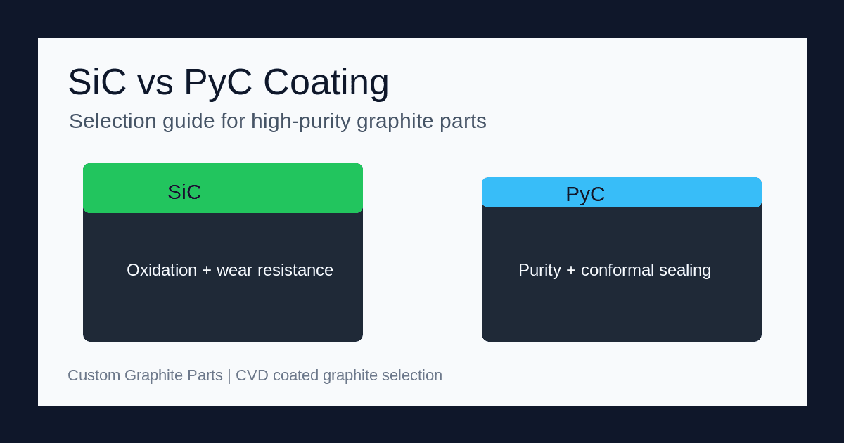
4. Visual Comparison: Coating Structures
Understanding how these coatings interact with the graphite substrate is crucial for predicting failure modes.
Schematic illustrating the relative thickness and structural differences between SiC and PyC CVD coatings.
5. Technical Comparison Table: SiC vs. PyC
To assist in immediate decision-making, the following matrix compares the verifiable operational limits of both coating technologies.
| Feature / Metric | Silicon Carbide (SiC) Coating | Pyrolytic Carbon (PyC) Coating |
|---|---|---|
| Typical Coating Thickness | 40 µm – 120 µm | 10 µm – 40 µm |
| Maximum Operating Temp (Vacuum/Inert) | ~1,600°C (sublimation risks higher up) | ~2,200°C+ |
| Maximum Operating Temp (Air/Oxidizing) | ~1,600°C | ~500°C (oxidizes rapidly) |
| Hardness (Vickers) | Very High (2,500 - 3,000 HV) | Low to Moderate |
| Purity Level (Ash Content) | High (< 5 ppm) | Ultra-High (< 1 ppm) |
| Reactivity to Corrosive Gases (HCl, NH3) | Excellent Resistance | Good, but susceptible to extreme halogens |
| Machinability Post-Coating | Cannot be machined (requires grinding) | Can be lightly polished, generally not machined |
| Relative Cost | High | Medium |
6. Engineering Selection Checklist
Do not guess which coating is appropriate. Run your application through this process of elimination checklist:
- Is the environment oxidizing? (Contains Oxygen, moisture, or air at high temps)
- If Yes: You must select SiC. PyC will burn away.
- Are aggressive halogen gases present? (e.g., HCl in Epitaxy)
- If Yes: SiC is strongly recommended for longevity and preventing substrate attack.
- Is absolute zero-silicon contamination required?
- If Yes: You must select PyC. SiC coatings can outgas trace silicon at extreme temperatures.
- Will the part experience high physical wear or high-velocity particle bombardment?
- If Yes: Select SiC for its exceptional hardness.
- Are you operating continuously above 1,700°C in a vacuum?
- If Yes: PyC is preferred, as SiC may begin to exhibit instability or react with the graphite substrate at ultra-high temperatures.
- Does the part have extremely tight dimensional tolerances that cannot accommodate thick buildups?
- If Yes: PyC is safer due to its thinner, more conformal deposition layer (10-40 µm).
7. The Danger of Spallation and CTE Matching
The number one cause of failure for coated graphite components is spallation (flaking or delamination of the coating).
This almost entirely comes down to a mismatch in the Coefficient of Thermal Expansion (CTE) between the base graphite and the CVD coating. If a procurement buyer purchases cheap, mismatched graphite from one supplier and sends it to a third-party for SiC coating, the part is almost guaranteed to fail prematurely during thermal cycling in the fab.
- SiC CTE: Typically around 4.0 - 4.5 x 10⁻⁶ /°C.
- Graphite CTE: Varies wildly depending on the grade, from 3.0 to 6.0 x 10⁻⁶ /°C.
The Solution: You must procure parts where the substrate graphite has been explicitly engineered and selected to match the CTE of the target coating. At our facilities, we utilize specialized grades of ultra-fine isotropic graphite specifically formulated to match the thermal expansion curve of our SiC and PyC CVD processes. This ensures the coating remains bonded even under extreme rapid heating and cooling cycles.
8. Engineering FAQ
1. Can a graphite part have both SiC and PyC coatings?
While theoretically possible, it is extremely rare and generally impractical. The differences in CTE and deposition processes make layering them prone to delamination. Engineers must choose the coating that solves their primary failure mode.
2. How does the coating affect the electrical conductivity of the graphite?
Bare graphite is highly conductive. PyC is also highly conductive. SiC, however, is a semiconductor. Depending on the purity and temperature, a SiC coating will significantly increase the electrical resistance at the surface of the part. If your process relies on electrical grounding through the graphite part, you must account for the SiC layer's resistance.
3. If the SiC coating chips, can the part be repaired?
Generally, no. Once the SiC layer is breached, the underlying graphite is exposed to the harsh environment. The aggressive gases will enter the breach and hollow out the graphite from the inside (often called "tunneling" or "wormholing"). Stripping and recoating is sometimes possible for very large, expensive susceptors, but for most consumables, the part must be replaced.
4. Why is Pyrolytic Carbon sometimes called Pyrolytic Graphite (PG)?
The terms are often used interchangeably in the industry. Technically, Pyrolytic Graphite refers to PyC that has been subjected to subsequent extreme heat treatment (annealing) to further align its crystalline structure into a true graphite lattice. For coating purposes on machined parts, PyC is the more accurate term.
9. Sourcing and Custom Solutions
Choosing between SiC and PyC is a high-stakes engineering decision. Procuring the raw graphite, machining it to tight tolerances, and successfully applying a flawless CVD coating requires an integrated, single-source supply chain.
If your facility is experiencing premature failure, spallation, or contamination from your current graphite consumables, our engineering team can help. We provide end-to-end manufacturing of custom CNC machined graphite parts, complete with perfectly CTE-matched SiC or PyC coatings tailored specifically for MOCVD, Epitaxy, and crystal pulling applications.
Contact our technical sales team today to discuss your process parameters and request an RFQ for coated graphite components.
10. References and Sources
To ensure the highest level of technical accuracy, the operational boundaries and material behaviors discussed in this guide are supported by data from the following industry and academic sources:
- Semicorex Advanced Material Technology: Technical specifications on CVD coating thicknesses in semiconductor thermal fields. View Source
- Toyo Tanso Technical Services: Comprehensive overview of surface treatments, including SiC and PyC chemical vapor deposition processes. View Source
- ResearchGate: Development and characterization of Silicon Carbide Coating on Graphite Substrate. Scientific analysis of erosion resistance and thermal stability. View Source
- Advanced Carbon Technologies: Pyrolytic graphite material properties, including CVD production and directional thermal/electrical behavior. View Source
Author
Graphite CNC machining, EDM electrode, mold tooling, and export-aware sourcing specialists.
Categories
More Posts
Copper vs. Graphite EDM Electrodes: A Cost and Performance Analysis
Should you use copper or graphite for your EDM electrodes? We break down the differences in machining speed, wear resistance, surface finish, and overall cost to help plastic mold shops make the best choice.
Graphite Rotors and Shafts for Aluminum Degassing: Wear Resistance and Lifespan Optimization
A comprehensive engineering and procurement guide to extending the lifespan of graphite degassing rotors in aluminum foundries. Learn about high-temperature oxidation, anti-oxidation coatings, material selection, and operational best practices.

Understanding Graphite Export Controls: What Global Buyers Need to Know in 2026
A practical guide to navigating China's export controls on high-purity and high-density artificial graphite. Learn how to secure end-user certificates, prevent supply chain disruptions, and manage lead times.