
TaC vs. SiC Coated Graphite Susceptors for GaN and SiC Epitaxy (MOCVD/CVD): Ammonia Corrosion Resistance, Wafer Pocket Flatness, CTE Delamination & Sourcing Guide
Compare TaC vs SiC coated graphite susceptors for epitaxy: corrosion, pocket flatness, CTE and lifetime costs. Request a drawing review and prepare your RFQ.
Engineering summary: For TaC vs SiC coated graphite susceptors, begin with the qualified reactor recipe and observed failure mode. CVD-SiC is an established protective coating for epitaxy; TaC is another candidate for demanding thermal environments. Neither material name establishes ammonia corrosion resistance, lifetime, wafer temperature uniformity or replacement compatibility. Select the complete graphite/coating system, specify finished pocket geometry, and validate it through representative process and cleaning cycles before changing production tooling.
Published and reviewed: November 13, 2026. Prepared by the Custom Graphite Parts Engineering Team for process engineers, equipment managers and purchasing teams sourcing globally. Scope: graphite wafer carriers, planetary disks and related MOCVD/CVD tooling for GaN and SiC epitaxy. This guide compares qualification questions rather than certifying a reactor-specific design.
Evidence and limits: The sources below establish manufacturer-described coating applications and the scope of two material test methods. They do not provide a controlled TaC-versus-SiC lifetime comparison in an identical ammonia recipe. The decision tables are engineering review aids, and worked calculations use explicitly hypothetical inputs. We report no original chamber trials, supplier audit results or measured device-yield improvements. Dimensions use millimetres or micrometres; temperature intervals and test conditions must accompany material-property reports.
For a drawing review, contact Custom Graphite Parts with your process envelope. Our SiC coated graphite susceptor page, high-purity graphite component guide, and isostatic graphite material page provide related sourcing context. An inquiry starts a feasibility review; coating capability and acceptance requirements need written confirmation.
1. Operating Environment: Separate GaN MOCVD from SiC CVD
GaN MOCVD and SiC epitaxy present different chemical environments. GaN recipes use ammonia as the nitrogen precursor and may use hydrogen or nitrogen carrier gases. SiC epitaxy uses silicon and carbon precursors, often with hydrogen; ammonia exposure should not be assumed for every SiC process. Cleaning and bake steps can impose a different exposure from the growth step. A comparison that combines all these environments into one maximum-temperature rating loses the information needed to choose a coating.
Record actual susceptor temperature, how it is measured, chamber pressure, gas composition, precursor flows, dwell time, ramps and cleaning sequence. Include whether a temperature refers to the heater, the susceptor or the wafer. An equipment setpoint cannot automatically be compared with a supplier's coupon-test temperature.
Start the investigation with the incumbent part. Photograph the locations of pits, flakes, cracks, deposits and exposed graphite; record cycle count and cumulative hot hours. Compare pocket edges, holes and upstream surfaces with protected regions. Apparent coating loss may involve chemical attack, mechanical handling, cleaning damage or deposited-film removal. This distinction determines what a replacement must improve and prevents attributing every defect to the coating chemistry.
2. Ammonia Corrosion Resistance: What the Evidence Supports
A dense CVD coating can reduce graphite exposure and the release of particles or impurities. Toyo Tanso describes SiC-coated graphite for semiconductor use, including suppression of reactions with ammonia, and describes its TaC-coated graphite as a dense heat-resistant barrier with improved adhesion. These are qualitative product statements, not a universal crossover temperature or guaranteed erosion rate. See the manufacturer's surface-treatment technical overview.
Consequently, do not reject SiC solely because a recipe contains NH₃, or accept TaC solely because a catalogue describes high heat resistance. The available sources do not support a blanket claim that SiC fails above 1150°C, that TaC is inert to 1800°C, or that one coating lasts a fixed multiple of the other. Surface condition, coating process, exposure duration and cleaning history remain part of the comparison.
Ask suppliers to identify the conditions behind any corrosion claim. A useful test report names the graphite grade, coating process and thickness, gas concentrations, flow, pressure, specimen temperature, duration, and measurement uncertainty. Mass change alone can conceal simultaneous deposition and erosion; combine it with surface inspection and a thickness or cross-section assessment where appropriate. Coupon results screen a candidate but do not establish coverage inside a full-size carrier's recesses and holes.
For the first qualification lot, agree on a representative exposure sequence and a stop criterion before testing. Monitor coating defects, particles and relevant contamination alongside thickness change. Keep ammonia-rich growth, hydrogen bake and cleaning exposures distinguishable in the records. If a supplier cannot disclose a proprietary recipe, require a documented statement of which customer process conditions its evidence covers and which remain untested.
3. Tooling Architecture and Wafer Pocket Cross-Section
The schematic identifies interfaces that must be reviewed together: graphite core, coating, pocket floor, wafer and gas gap. It is conceptual, not to scale, and does not specify a universal coating thickness, support arrangement or operating temperature. Some reactors use shaped pockets or peripheral supports; use the equipment-approved geometry as the starting point.
4. CTE Matching and Interfacial Delamination
Thermal expansion mismatch can put a ceramic coating in tension or compression during deposition cooldown and operating cycles. Evaluate the substrate and coating as a system: graphite grade and orientation, temperature-dependent expansion, coating thickness, geometry, adhesion and process history all matter. A single room-temperature CTE value cannot establish that a finished part will survive cycling.
For a simplified, fully bonded, thin elastic coating on a much thicker substrate, the change in biaxial coating stress can be screened as:
Change in coating stress ≈ E_coating / (1 - nu_coating)
                         × integral from T_reference to T_final
                           of [alpha_substrate(T) - alpha_coating(T)] dT
Here E is Young's modulus, nu is Poisson's ratio, and alpha is the instantaneous linear expansion coefficient. The reference is an assumed stress-free state; it is not automatically room temperature or the nominal deposition temperature. The model excludes deposition stress, creep, cracking, interlayers and stress concentration at edges, so it cannot predict a safe stress or a service-life limit.
Illustrative mismatch calculation: Assume a constant substrate-minus-coating CTE difference of −2 × 10⁻⁶/K during a cooldown of −1000 K. The mismatch strain is (+0.002), or 0.2%. Under the model, this tends to put the coating in tension. Reversing the mismatch sign tends toward compression. Neither sign proves failure: tensile cracking and compression-driven delamination also depend on fracture and adhesion properties.
Request expansion curves measured over the relevant interval, together with graphite orientation and test uncertainty. ASTM E228 covers push-rod dilatometry; it does not prescribe an acceptable graphite CTE window for TaC. A mean expansion value over one interval must not be substituted for an instantaneous curve over another without justification. Require the coating supplier to qualify its substrate grade rather than mandating an unsupported generic “CTE-matched” range.
5. TaC vs SiC: Procurement Decision Matrix
This eight-row comparison converts material claims into acceptance questions. It is a qualification framework, not measured comparative performance. Keep the incumbent SiC part as the baseline when evaluating a TaC alternative, including its known limitations.
| Decision factor | SiC-coated graphite candidate | TaC-coated graphite candidate | Evidence to request |
|---|---|---|---|
| GaN ammonia exposure | Assess against the actual NH₃ recipe | Assess the proposed barrier under the same recipe | Gas, pressure, temperature, time and surface-change records |
| SiC epitaxy environment | Review hydrogen, precursors and cleaning separately | Review the same exposures before substitution | Process-specific compatibility statement and trial plan |
| Graphite substrate | Specify the supplier-qualified grade | Require compatibility with the selected TaC process | Grade identity, purity and expansion data |
| Coating coverage | Inspect edges, bores and recesses | Inspect the same regions and any interlayers | Thickness map, coverage method and defect acceptance criteria |
| Thermal cycling | Use incumbent crack and flake history | Establish equivalent cycle evidence | Ramp, dwell, cooldown and inspection records |
| Pocket geometry | Inspect after final coating | Recalculate allowances for the proposed coating | Finished drawing, datum scheme and profile report |
| Temperature measurement | Preserve the qualified optical setup | Revalidate after changing surface optical properties | Pyrometer method and calibration records |
| Cost per accepted wafer | Use actual purchase and maintenance records | Include qualification and changeover costs | Comparable quotations and measured accepted output |
A higher purchase price can be justified by longer qualified service, lower replacement burden or improved accepted output. Those benefits require evidence from your process; they should not be inferred from a melting point, coating colour or generic catalogue rating.
6. Wafer Pocket Flatness, Gas Gap and Finished Dimensions
Wafer heating can combine radiation, gas conduction and local solid contact. Pocket profile, wafer bow, support arrangement, pressure and gas composition all influence the effective gap. Cold-state pocket flatness and hot-state wafer shape are different measurements. A nominal five-micrometre flatness requirement does not establish a particular wafer temperature gradient or device yield.
A simplified gas-conduction model has heat flux proportional to gas conductivity times temperature difference, divided by an effective gap. Rarefaction and surface accommodation can require additional corrections. A radiation calculation also needs absolute temperatures in kelvin and optical assumptions. Use such models for sensitivity analysis, then validate temperature uniformity with an equipment-appropriate measurement method.
Pocket metrology and acceptance matrix
Specify these six features on the finished coated drawing. Limits belong to the approved design and demonstrated measurement capability; wafer diameter alone cannot supply them.
| Feature | What must be defined | Inspection evidence |
|---|---|---|
| Pocket diameter | Finished diameter, clearance, measurement temperature and edge geometry | Calibrated dimensional report with uncertainty |
| Pocket depth | Reference rim or datum, support surfaces and coating allowance | Depth/profile scan tied to the drawing datums |
| Floor shape | Flat, concave or other intended profile; evaluation area and edge exclusion | Full profile map rather than only a centre reading |
| Floor roughness | Parameter, filter, evaluation length and allowed defects | Trace or optical map with method and settings |
| Runout and overall shape | Mounting datum, support fixture and relevant rotating surfaces | Fixture description and runout/profile report |
| Holes and transitions | Finished bore size, radii, chamfers and masked surfaces | Coverage inspection and dimensions after coating |
Do not apply wafer-flatness terminology to a susceptor pocket without defining what is measured. Agree on sampling, support conditions, instrument resolution and measurement uncertainty before setting micrometre-level acceptance limits. Also distinguish the roughness measurement from long-wavelength form: a smooth surface can still have the wrong pocket profile.
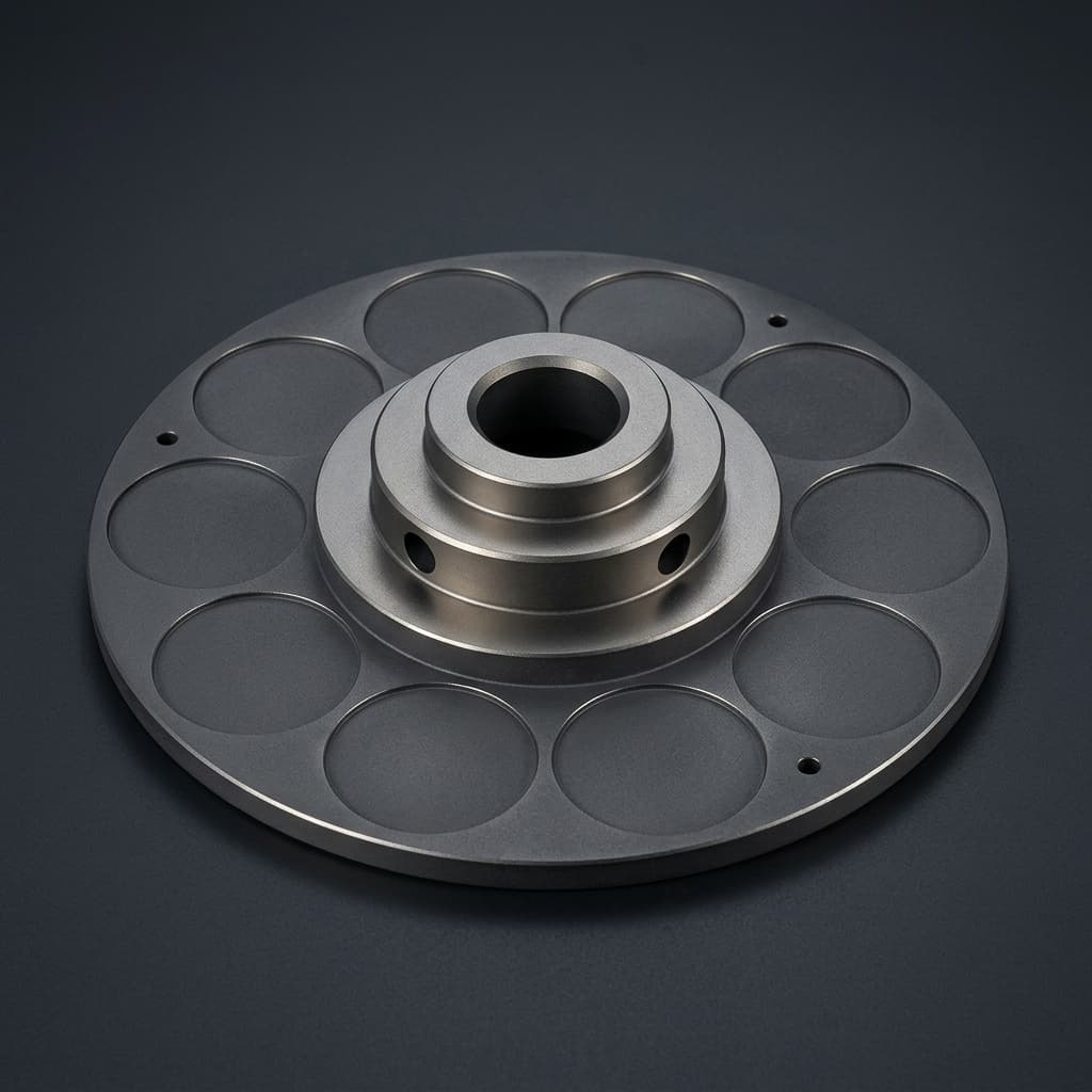
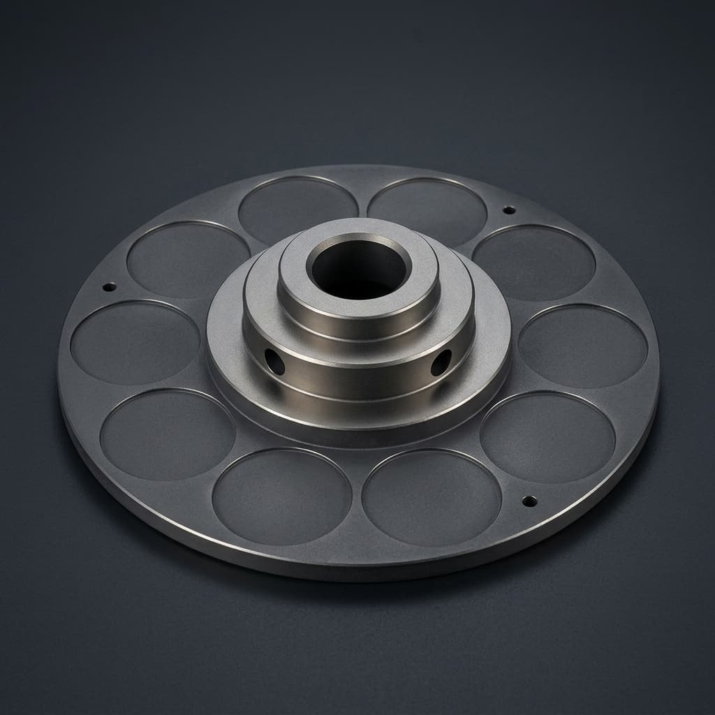
Illustrative catalogue image of a multi-pocket carrier. Appearance does not verify coating composition, purity, dimensions or process qualification; request the drawing and inspection records for the quoted part.
Coating allowance: diameter and depth use different datums
For a cylindrical pocket with uniform coating on opposing sidewalls, the finished diameter is the machined diameter minus twice the sidewall thickness. For depth measured from a coated top rim to a coated floor, both surfaces move:
D_finished = D_machined - 2 × t_sidewall
h_finished = h_machined + t_top - t_floor
Illustrative example: A 35 µm coating on each sidewall reduces the pocket diameter by 70 µm. If the rim and floor both receive 35 µm, their equal buildup leaves the nominal depth unchanged. If the rim is masked, the same floor buildup reduces depth by 35 µm. These are geometric calculations, not a statement of attainable thickness uniformity. Distinct rim, wall and floor thicknesses must be included where deposition is nonuniform.
If these datum or coating assumptions are missing from your model, request a drawing review before releasing a purchase order. Mark whether the STEP model describes the graphite preform or the finished coated part.
7. Pyrometer Emissivity and Recipe Transfer
Changing a coating can change the radiation received by a pyrometer. The effect depends on wavelength, temperature, roughness, surface deposits, optical access and whether the instrument measures the wafer or the susceptor. A catalogue's total emissivity is not automatically the spectral emissivity needed by your instrument.
For a simple single-colour instrument viewing a surface through unchanged optics, lower actual emissivity than the configured value tends to produce an underestimated temperature. A closed-loop controller could then increase heater power. The magnitude cannot be specified without the instrument and process conditions, and multiwavelength compensation methods have different assumptions.
Before recipe transfer, document the incumbent optical configuration and the replacement coating's relevant data. Agree with the equipment and metrology teams how to verify temperature and uniformity during qualification. Retain window condition, calibration settings and deposited-film state in the records. Do not promise a fixed correction in degrees Celsius or transfer an incumbent setting solely because the replacement has the same shape.
8. Refurbishment Economics and Qualification Cost
Refurbishment is viable only if the coating supplier has a qualified removal and recoating route for that exact graphite/coating combination. Ask whether removal attacks the substrate, changes pocket dimensions, leaves residues or affects subsequent adhesion. Require a post-removal dimensional assessment, cleaning plan and acceptance criteria before treating a used core as reusable. This guide does not establish a stripping chemistry or a guaranteed number of refurbishment cycles.
Evaluate economics on accepted output, using the same accounting boundary for both candidates:
Cost per accepted wafer =
  (tool purchase + allocated qualification + replacement downtime
   + cleaning/refurbishment + disposal costs)
  / accepted wafers processed over the qualified tool life
Avoid double-counting downtime and lost output. Track scrap and requalification consistently, and separate a reusable graphite core from recurring coating charges. For global quotations, also compare currency, delivery terms, packaging, lead time, minimum quantity, warranty boundaries and the cost of keeping a spare.
Hypothetical break-even example, not a supplier quote or lifetime claim: Assume a SiC part costs USD 2,000, incurs USD 500 in replacement burden, and delivers 100 accepted runs. Its tooling cost is USD 25 per accepted run. A TaC candidate at USD 5,000 plus the same USD 500 burden must exceed 220 accepted runs to improve that figure, assuming equal accepted wafers per run and no additional qualification cost. At 250 accepted runs, it would cost USD 22 per run. Replace every input with your own records; fewer accepted wafers or extra qualification expense can reverse the result.
9. Ten-Point RFQ Checklist for Engineering and Purchasing
Use this checklist with the approved drawing and process envelope. The purpose is to obtain comparable offers with explicit exceptions, rather than impose unsupported universal tolerances.
- 1. Part identity: State reactor model, approved part reference, drawing revision, wafer size, quantity and replacement interfaces. Require the supplier to identify any unverified compatibility assumptions.
- 2. Process envelope: Provide growth, bake and cleaning gases, pressure, temperature, dwell and ramps. Distinguish GaN ammonia exposure from SiC precursor chemistry.
- 3. Graphite grade and purity: Specify the qualified substrate and critical elemental limits. Request lot traceability and a suitable assay such as GDMS with detection limits. Total ash alone does not establish individual contaminant levels.
- 4. Expansion and cycling: Request relevant CTE data and evidence for the complete coating/substrate system. Define a representative cycle test and inspection points.
- 5. Coating specification: Name the coating process, composition, nominal thickness, allowed variation, coverage and masked regions. Agree on how thickness is measured on this geometry.
- 6. Finished metrology: Attach the pocket and mounting datum scheme, profile and roughness requirements, measurement method, sampling plan and uncertainty expectations.
- 7. Defect integrity: Define allowed cracks, pinholes, flakes and exposed graphite, plus the inspection method and detection capability. A leak test needs a validated fixture and an agreed criterion; it is not automatically valid on every carrier.
- 8. Handling and packaging: Specify an agreed cleaning process, drying, packaging cleanliness, transport protection and incoming inspection. Confirm these steps are compatible with the coating.
- 9. Optical and process validation: Identify the temperature-measurement method, required optical data and ownership of recipe recalibration. Require written approval before production substitution.
- 10. Commercial and refurbishment terms: Compare first-article scope, lead time, delivery terms, nonconformance handling, recoating eligibility and spare-part availability. Record supplier exceptions before order release.
Bulk density can help identify and control a graphite grade. ASTM C559 addresses bulk-density measurement of manufactured carbon and graphite articles; it does not measure pore-size distribution, establish purity or certify a coated part's leak integrity.
10. Frequently Asked Questions
Does ammonia automatically rule out SiC-coated graphite for GaN MOCVD?
No. SiC-coated graphite is used in semiconductor processing, and the cited manufacturer describes ammonia-reaction suppression. Suitability still depends on the exact recipe and qualified coating system. Request comparable exposure evidence rather than treating a single temperature as a universal failure threshold.
Can any isostatic graphite grade be coated with TaC?
Coating feasibility does not establish service suitability. The supplier must qualify the substrate grade, coating process, geometry and thermal cycle together. Expansion mismatch is one consideration alongside adhesion, residual stress and defects; this guide specifies no universal acceptable CTE window.
Does a flatter pocket always improve wafer temperature uniformity?
No. The required shape depends on wafer bow, support conditions and reactor design. A deliberately profiled pocket can differ from a flat plane. Inspect against the approved drawing and verify thermal performance independently; do not convert cold flatness directly into a guaranteed temperature spread.
When is TaC cheaper than SiC over the tool life?
When its total cost divided by accepted output is lower under comparable conditions. Use measured life, maintenance, downtime, qualification costs and accepted wafers. The worked example above illustrates the arithmetic and supplies no calendar payback promise or market price benchmark.
How should pinholes and coating defects be inspected?
Agree on a method suited to the coating and geometry, with documented detection capability. Visual or microscopic mapping, representative cross-sections and validated integrity tests answer different questions. Destructive checks belong on approved samples or coupons; do not classify an unqualified chemical exposure as nondestructive acceptance testing.
Can worn TaC susceptors be stripped and recoated?
Ask the original coating supplier. Reuse requires a validated removal route, sufficient remaining material, acceptable contamination and a finished-dimension recovery plan. A reusable core or a fixed number of recoating cycles should not be assumed when comparing quotations.
Can coating colour prove TaC composition or explain a defect?
No. Lighting, roughness, deposits and surface condition affect appearance. Record a colour change as an observation and investigate it with appropriate surface or composition analysis. A photograph alone cannot establish stoichiometry, oxidation, adhesion or contamination.
How does coating thickness change pocket depth?
Depth depends on both the reference rim and the floor. Equal coating buildup on both leaves their nominal separation unchanged. A masked rim with a coated floor reduces the depth by the floor buildup. Specify the finished datum scheme and allow for actual local thickness variation.
11. Request an Engineering Review and Tooling Quotation
Send the current 2D drawing and STEP model, reactor interface, wafer size, process envelope, observed incumbent failure mode, quantity and delivery destination through our contact page. Identify the first-article reports you require and which acceptance criteria still need discussion. This allows a useful feasibility response before a production quotation.
Review our SiC coated graphite susceptors, high-purity graphite components, and isostatic graphite grades alongside the RFQ. Obtain written confirmation of the proposed coating route, substrate, tolerances and qualification responsibilities. A quotation or drawing review does not replace your equipment owner's approval for a production change.
12. Sources and Test-Method References
Source review: November 13, 2026. These public technical and catalogue pages were checked for the specific scope described below. Full standards procedures may require licensed access; the catalogue entries do not demonstrate that a supplier has performed those tests. Review this guide again when the recipe, drawing, supplier process or referenced method changes.
- Toyo Tanso — Purity and Surface Treatment in Semiconductor Manufacturing. Manufacturer technical overview. Describes SiC and TaC surface treatments and their intended protective roles. It does not substantiate the corrosion rates, fixed run counts or universal temperature limits sometimes used in material comparisons, and it is not evidence of Custom Graphite Parts' manufacturing capability.
- ASTM E228-22 — Standard Test Method for Linear Thermal Expansion of Solid Materials With a Push-Rod Dilatometer. Official E228 catalogue. Relevant to expansion measurements. Applicability and measurement capability must be demonstrated for the chosen temperature interval; this method does not approve a coating/substrate pairing.
- ASTM C559-16(2020) — Standard Test Method for Bulk Density by Physical Measurements of Manufactured Carbon and Graphite Articles. Official C559 catalogue. Relevant to substrate bulk density, not pore-size distribution, coating adhesion or finished-carrier flatness.
Author

Graphite CNC machining, EDM electrode, mold tooling, and export-aware sourcing specialists.
More Posts
Graphite Bipolar Plates for PEM Fuel Cells and Electrolyzers: CNC Micro-Channel Machining, Resin Impregnation, Gas Permeability & Clamping Tolerances Guide
Specify graphite bipolar plates for PEM fuel cells: compare CNC routes, resin sealing, leak tests and clamping tolerances. Prepare drawings for a DFM review.
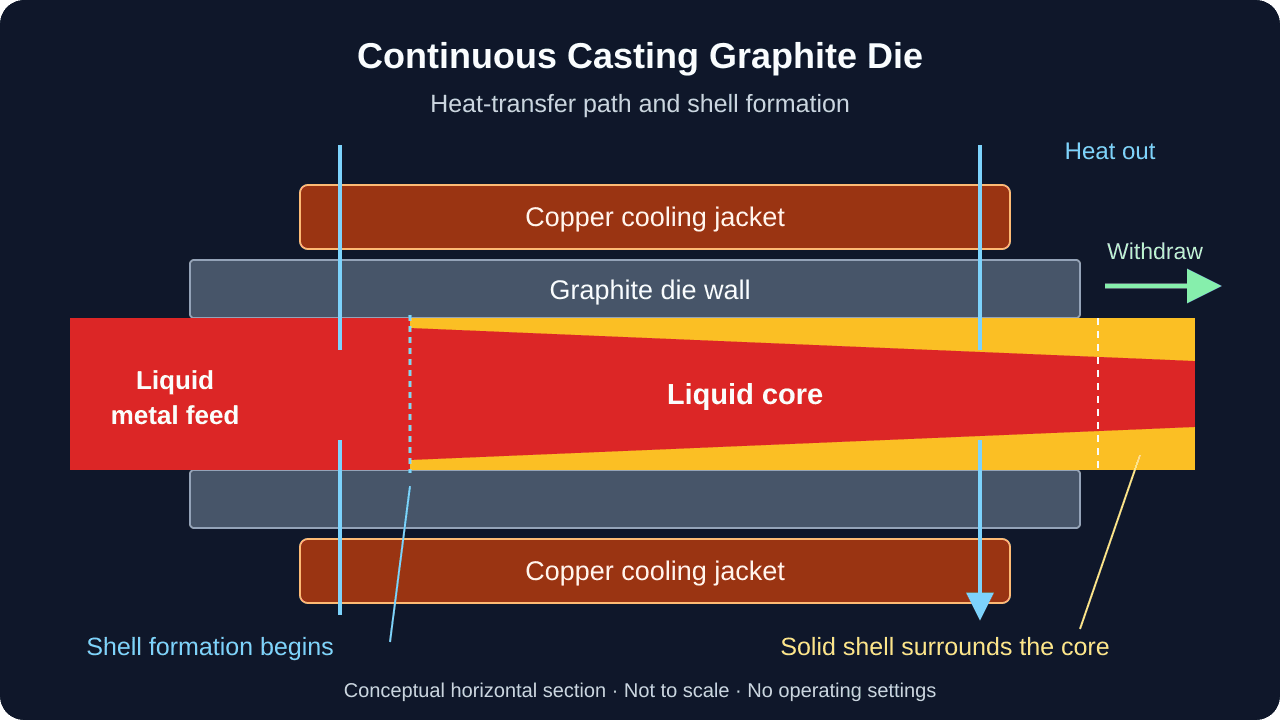
Continuous Casting Graphite Dies: Grain Selection, Bore Tolerances, Freeze-Line Control & Alloy Wear Life Guide
Compare continuous casting graphite dies for copper, brass and bronze. Check grain data, bore tolerances, freeze-line risks and wear-life trials for your RFQ.
Mid-2026 Graphite Supply Chain Update: Section 301 Tariffs, EV Demand, and Sourcing Strategies
Mid-2026 graphite supply chain update for custom graphite buyers: Section 301 dates, EV demand, China-light sourcing limits, and RFQ actions.