
Continuous Casting Graphite Dies: Grain Selection, Bore Tolerances, Freeze-Line Control & Alloy Wear Life Guide
Compare continuous casting graphite dies for copper, brass and bronze. Check grain data, bore tolerances, freeze-line risks and wear-life trials for your RFQ.
Selection answer: Choose continuous casting graphite dies by alloy, strand shape and casting-machine design first. Then compare the named grade's grain size, thermal conductivity, porosity and strength, and agree on the bore profile, surface finish and cooler fit. Finer grain, higher density or lower ash alone does not identify the best die. Qualify wear life on your line against a defined strand-quality limit before placing a repeat order.
Published and technically reviewed: October 28, 2026. This guide is for foundry engineers and technical buyers sourcing copper, brass and bronze tooling globally. Dimensions use SI units. Precious metals, nickel alloys and cast iron require separate alloy and machine qualification; this guide does not supply operating settings for them.
Evidence and limits: We compare the manufacturer documents linked below and turn their selection factors into drawing checks, an RFQ checklist and a reproducible wear-life evaluation. No production trials or customer die-life measurements are reported here. Published material properties are typical values, not guarantees of an individual blank or finished die.
For an existing drawing or replacement program, request a continuous casting tooling review. Include the alloy, machine configuration, drawing revision and current failure mode. Our continuous casting graphite tooling page describes the sourcing scope; the custom graphite mold page covers related tooling.
1. Freeze-Line Control: Match Heat Extraction to Shell Formation
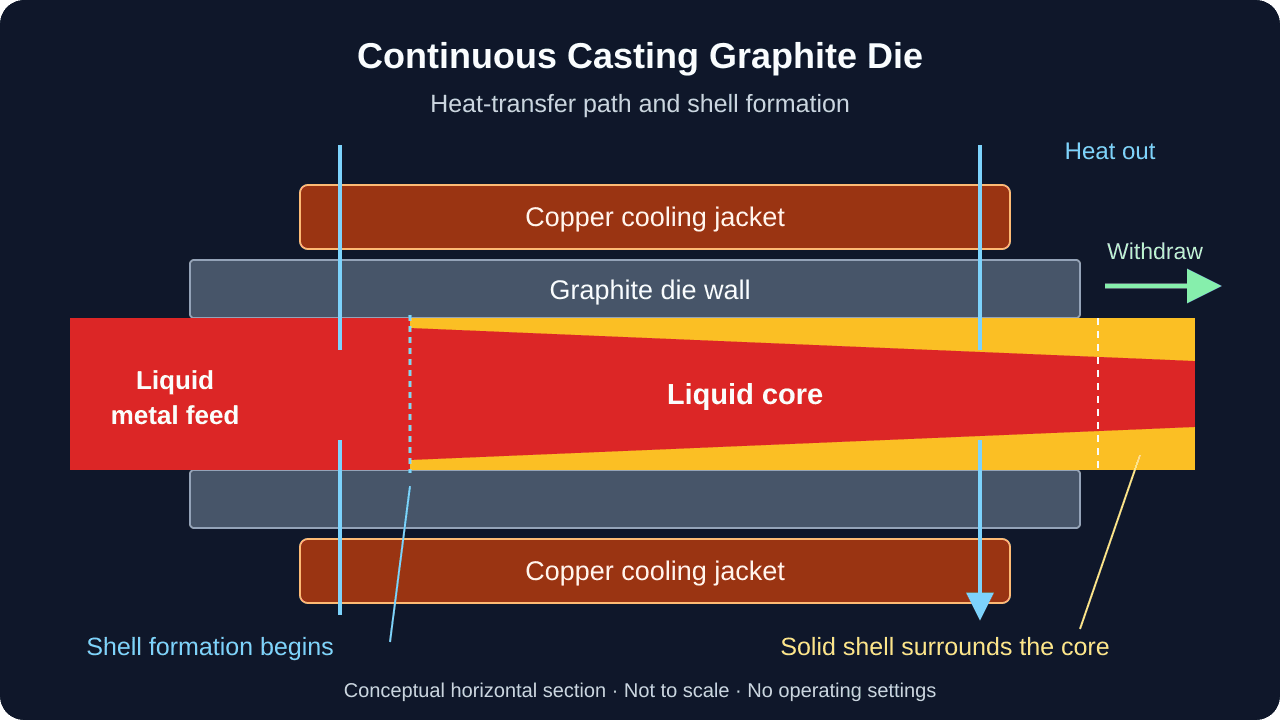
The solidification front is the boundary at which a solid shell develops around the liquid core. Operators may call its position the freeze line. It is distinct from a free liquid-surface meniscus. Its position depends on melt superheat, withdrawal cycle, strand section and the complete heat-transfer path through the shell, graphite, die-to-jacket interface and coolant.
SGL Carbon's casting overview describes upward, horizontal and downward withdrawal, usually with a core that remains liquid. A fully solid strand at the die exit is therefore not a universal acceptance requirement. The shell must instead be adequate for the machine's validated withdrawal, support and downstream cooling arrangement.
- Solidification too close to the inlet: Investigate entry restriction, shell sticking, extraction-force changes and chatter together with the approved cooling and withdrawal records.
- Insufficient shell development near the exit: Investigate heat-removal capacity, interface contact, coolant condition and withdrawal rate. Scoring alone does not identify the cause.
- Uneven shell growth: Compare circumferential wear, die wall thickness, alignment and jacket condition before changing graphite grade.
Compare the defective run with a known acceptable run. Record actual melt temperature, coolant inlet/outlet temperatures and flow, withdrawal settings, strand dimensions and defect location. Review changes within the machine supplier's operating procedure; this guide cannot prescribe a universal temperature, flow or pause-time correction.
2. Crystallizer Assembly: Read the Heat-Transfer Path
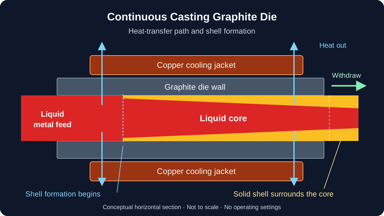
Original explanatory schematic, not to scale or a production photograph. It shows a horizontal section through one possible assembly. The shell grows along the bore while a liquid core may continue beyond the die. Jacket geometry, taper and cooling layout depend on the machine.
Follow the heat path from metal to graphite to jacket to coolant. A material with greater thermal conductivity cannot compensate for a poor interface, an unsuitable bore profile or a fouled cooler. Specify and inspect these interfaces as part of the same assembly rather than purchasing a graphite blank by density alone.
3. Grain Size, Density and Porosity: Compare Named Grades
Fine grain can help produce detailed geometry and a consistent machined surface. Isostatic graphite is a useful starting point for many precision dies, but forming method alone does not approve or reject a casting grade. Ask for its published casting application, directional properties and the manufacturer's recommendation for the actual alloy and section. See our isostatic graphite overview and molded and extruded graphite guide for the material families.
Do not treat grain size as pore size or bulk density as a permeability measurement. Two graphites can have similar density while differing in pore entrances, permeability, strength and heat transfer. Compare measurements made with the same method and temperature; a hardness number without its scale and test load is incomplete.
For example, the published SIGRAFINE R4510 datasheet lists a 10 µm grain size, while the R4810 datasheet lists 20 µm. Both identify continuous casting as an application. Their published range illustrates why a grain-size limit must be justified for the particular application. Their property comparison appears in Section 7.
For electrical copper, agree on allowable contamination and the evidence needed to control it. Request grade-specific ash data and any required impurity analysis. A universal purification threshold cannot establish finished-rod conductivity or replace rod testing against the buyer's product specification.
4. Alloy-Specific Wear: Copper, Brass and Bronze
The Mersen metallurgy brochure, PDF page 3 treats copper, brass and bronze separately. It highlights wear resistance for copper, zinc vaporization for brass, and heat removal and porosity for bronze. These are manufacturer selection considerations, not proof that one density or grade works for every line.
Copper: Balance Wear Resistance and Heat Transfer
Record whether the feed is oxygen-free, ETP or deoxidized copper, along with the required rod properties. Compare bore scoring, oxidation and dimensional drift with actual extraction conditions. Ask the supplier to justify its grade for the product shape as well as the alloy; wire and strip need not use the same material. Higher thermal conductivity alone does not establish longer life.
Brass: Include Vapor Transport and Pore Structure
For a zinc-bearing alloy, ask how the proposed grade balances vapor transport, heat extraction and resistance to metal penetration. Do not select a nominally "gas-tight" or "high-porosity" blank without application evidence. Pure zinc's boiling point alone cannot determine vapor behavior in a multicomponent brass melt. Record deposits, bore wear and melt/atmosphere conditions when comparing replacements.
Bronze: Qualify the Exact Chemistry and Section
Identify tin content, phosphorus or other alloying additions and whether the product is rod, tube or strip. Do not assume that every bronze shares one abrasive wear mechanism. Compare surface scoring, bore enlargement and strand defects at matched cooling and withdrawal conditions. A hardness increase is useful only if strength, heat transfer and machinability still meet the application.
For other alloys, obtain a separate recommendation. A precious-metal casting claim does not establish graphite compatibility with every gold, silver or platinum-bearing composition.
5. Bore Tolerances, Taper and Finish: Make the Drawing Inspectable
The purchase drawing should define the cold inspection geometry and the machine interface. Do not convert a bulk solidification-shrinkage percentage directly into a bore taper: volumetric contraction, local diameter change and thermal expansion of the tooling are different quantities. Retain a proven profile unless a reviewed redesign and trial justify changing it.
- Bore profile: Define the inlet, active zone and outlet with axial stations. State whether taper is a diameter change or a per-side angle, its direction, its reference length and the inspection temperature.
- Bore size: Specify the nominal diameter, tolerance and measurement positions. Record roundness and size at more than one orientation where the drawing requires it.
- Surface finish: Specify Ra, measurement direction, evaluation conditions and accessible inspection locations. Agree on permitted surface lay and edge condition. An Ra value alone does not establish friction or prevent strand tearing.
- Cooler interface: Provide the jacket drawing and fit requirement, including assembly temperature and method. Clearance or interference must be approved for that assembly rather than copied from a generic tolerance table.
- Geometric control: Define the datum axis, runout or position control, face requirements and gauging setup. Concentricity and total indicated runout are not interchangeable callouts.
Illustrative drawing check, not a machining recommendation: If a bore decreases from Ø20.00 mm to Ø19.98 mm over 100 mm, the diametral taper is 0.02 mm per 100 mm and the radial change is 0.01 mm. Labeling the same drawing only "0.02 taper" leaves a factor-of-two ambiguity. These example dimensions do not specify the correct taper for copper or any other alloy.
Our graphite CNC machining design guide and tolerances provides related drawing guidance. For a long or small bore, ask for a drawing and inspection review before fixing a tolerance or finish that the proposed process cannot verify.
6. Upward, Horizontal and Vertical Downward Configurations
Upward Casting, Including UPCAST® Systems
Confirm the cooler and die interface, immersion arrangement, withdrawal cycle and machine drawing revision. Use the equipment supplier's approved dimensions and settings; there is no universal immersion depth or pull-pause-reverse timing for all upward lines. UPCAST® identifies a proprietary technology, not all upward casting machines, and this guide implies no affiliation or replacement approval.
Horizontal Casting
Include the furnace or tundish connection, sealing faces and withdrawal alignment. Keep worn-die orientation marks so upper and lower bore wear can be compared. Circumferential asymmetry is a reason to inspect the assembly and operating record, not automatic evidence that the graphite grade is wrong.
Vertical Downward Casting
Confirm the shell-support arrangement, metal head, withdrawal path and secondary cooling interfaces. Do not transfer a profile from a small upward rod die to a larger downward billet without review. Mechanical integrity and heat removal must be evaluated for the actual section and machine.
7. Technical Comparison Matrix: Published Graphite Properties
The following two manufacturer grades illustrate the property trade-offs. Values come from the single-page SGL datasheets linked in Section 3: R4510, TDS R4510.01 (December 2020), and R4810, TDS R4810.00 (April 2019). They are typical averages; the supplier warns that individual block values vary with dimensions and format. Availability and alloy-specific die life require confirmation with the supplier.
| Property | SIGRAFINE R4510 | SIGRAFINE R4810 | How to use the comparison |
|---|---|---|---|
| Average grain size, ISO 13320 | 10 µm | 20 µm | Compare machining detail needs; do not infer pore size. |
| Bulk density, DIN IEC 60413/204 | 1.83 g/cm³ | 1.82 g/cm³ | Similar density does not establish equivalent performance. |
| Open porosity, DIN 66133 | 10 vol.% | 11 vol.% | Read alongside permeability and alloy-contact evidence. |
| Medium pore entrance diameter, DIN 66133 | 1.8 µm | 3.3 µm | Distinguish pore entrances from average grain size. |
| Permeability coefficient at ambient temperature, DIN 51935 | 0.06 cm²/s | 0.3 cm²/s | Compare under the stated test method, not as a hot-melt flow rate. |
| Flexural strength, DIN IEC 60413/501 | 60 MPa | 45 MPa | Ask how the blank and finished wall section are qualified. |
| Thermal conductivity at 20°C, DIN 51908 | 110 W/(m·K) | 140 W/(m·K) | Request operating-temperature data for thermal analysis. |
| Thermal expansion over 20–200°C, DIN 51909 | 4.2 × 10⁻⁶ K⁻¹ | 4.1 × 10⁻⁶ K⁻¹ | Do not extrapolate directly to molten-metal temperature. |
| Ash content, DIN 51903 | 200 ppm | 50 ppm | Agree on any additional impurity limits and certification. |
Selection judgment: These data show trade-offs, not a universal winner. Shortlist grades with the manufacturer using alloy, shape, wall section and line conditions, then verify the proposed blank and trial die. Our graphite grade comparison provides broader material-selection context.
How to Qualify Alloy Wear Life
- Set the end-of-life rule first: Agree on maximum strand dimensional drift, surface defects, bore wear or another measurable rejection limit. Record the inspection method and sampling interval.
- Record a baseline: Keep the die grade and lot, drawing revision, starting bore measurements, alloy/heat identification, jacket condition and approved line settings.
- Separate productive running from downtime: Log cast length, accepted output, operating hours, starts and stops, and the reason for removal. A planned shutdown does not establish wear-out life.
- Compare like conditions: Report accepted metres or tonnes per die and cost per accepted tonne as well as operating hours. Repeat comparable runs and retain the spread; a single run cannot establish a guaranteed replacement interval.
Worked arithmetic example — hypothetical, not a trial result: A die costing $240 that produces 30 accepted tonnes has a tooling cost of $8/t. A $300 die producing 50 accepted tonnes costs $6/t. This comparison excludes downtime, remachining and freight. The second die is economically better only if the assumed output and comparable strand quality are demonstrated on the line; purchase price or hours alone cannot establish that result.
8. Seven-Point Technical RFQ and Inspection Checklist
- Alloy and product: Exact alloy designation/composition, required strand dimensions, product acceptance standard, contamination limits and actual approved casting temperature range.
- Machine and cycle: Manufacturer/model, upward/horizontal/downward configuration, drawing revision, withdrawal speed and applicable pull, dwell and reverse settings.
- Bore profile: Dimensioned axial stations, taper convention and direction, inlet/outlet details, datum scheme and cold inspection temperature.
- Finish and inspection: Required Ra, measurement direction and method, surface-lay acceptance, edge/chip criteria and access for bore inspection.
- Material traceability: Named manufacturer grade or documented proposed equivalent, relevant property/test methods, lot identification, ash or impurity requirements and agreed certificates.
- Jacket interface: Mating bore and tolerance, approved fit and assembly procedure, sealing faces, wall section and geometric inspection requirements.
- Qualification and delivery: Trial quantity, wear/strand-quality acceptance criteria, reporting and removal rules, protective packaging, supplier drying/startup instructions, spare quantity and destination country.
Keep the trial acceptance record separate from routine purchase acceptance. A material certificate verifies specified material data; it does not prove the finished die will meet an untested service-life target.
9. Frequently Asked Questions
What grain size should a continuous casting graphite die use?
Use a named grade recommended for the alloy, section and line. The two published continuous-casting grades above have 10 µm and 20 µm average grain size. Finer grain can help machining detail, but a below-5-µm requirement is not universal. Review porosity, permeability, conductivity and strength together.
What bore tolerance and Ra should I put on the RFQ?
Use the qualified die drawing and inspection capability. There is no universal ±0.010 mm bore tolerance, runout limit or Ra ≤ 0.2 µm finish for every diameter and length. Identify the measurement stations, datum, surface lay and test conditions; have the supplier confirm achievable and inspectable limits before order acceptance.
Why does brass need a different graphite grade from copper?
Zinc-bearing brass introduces vapor-transport considerations alongside wear and heat transfer. Request application evidence for the exact brass and product shape. Neither maximum density nor maximum porosity alone proves suitability, and a brass-versus-copper life ratio needs comparable operating records.
What should I check when the strand shows ring cracks or chatter?
Compare the approved withdrawal cycle, force trends if recorded, melt/cooling records, bore condition and alignment with an acceptable run. These defects can have several causes. Do not apply a generic temperature increase or reverse-stroke change from an article; use the machine supplier's troubleshooting procedure.
Can a worn graphite die be remachined and reused?
Possibly, after inspection for cracking, oxidation, metal penetration, remaining wall thickness and jacket compatibility. Reboring changes geometry and heat transfer. Obtain approval for the revised drawing and requalify it; a larger bore does not automatically make a worn die suitable for the next product size.
How many hours should a graphite casting die last?
There is no defensible universal hour range across copper, brass and bronze lines. Ask for comparable alloy, section, operating conditions, removal criteria and run records behind a life claim. Use Section 7's trial method to establish your own replacement interval and cost per accepted tonne.
10. Request a Continuous Casting Tooling Review
Send Custom Graphite Parts the current die and jacket drawings, alloy, machine configuration, annual quantity and observed wear pattern through our engineering inquiry page. Include photos with orientation and measured bore wear if available. State whether the request is a drawing-controlled replacement, a proposed material substitution or a redesigned trial die.
Ask the quotation to identify the proposed grade, inspection scope, certificates, lead time and any qualifications required before repeat production. Bore tolerances, finish, purification and remachining feasibility must be confirmed for the specific drawing rather than assumed from this guide. See the continuous casting tooling program for related supply options.
11. Sources and Technical Boundaries
Sources checked on October 28, 2026. The manufacturer publication dates below describe the documents, not new 2026 material tests. These sources support material and process selection; none establishes the service life of a Custom Graphite Parts die.
- SGL Carbon — Graphite Dies and Molds for Continuous Casting. Application scope, withdrawal directions, shell/liquid-core description and selection by alloy, shape and plant conditions.
- SGL Carbon — SIGRAFINE R4510 technical datasheet, page 1, TDS R4510.01, December 2020. Source of the R4510 values in Section 7 and the manufacturer's typical-value limitations.
- SGL Carbon — SIGRAFINE R4810 technical datasheet, page 1, TDS R4810.00, April 2019. Source of the R4810 values in Section 7, including conductivity at 20°C and expansion over 20–200°C.
- Mersen — Graphite Specialties Solutions for Metallurgy, PDF pages 2–3. Heat-extraction principles and separate selection considerations for copper, brass, bronze and nickel alloys. Manufacturer recommendations require confirmation for the exact alloy and machine.
Author

Graphite CNC machining, EDM electrode, mold tooling, and export-aware sourcing specialists.
Categories
More Posts
Graphite Bipolar Plates for PEM Fuel Cells and Electrolyzers: CNC Micro-Channel Machining, Resin Impregnation, Gas Permeability & Clamping Tolerances Guide
Specify graphite bipolar plates for PEM fuel cells: compare CNC routes, resin sealing, leak tests and clamping tolerances. Prepare drawings for a DFM review.
Carbon-Carbon (C/C) Composites vs. Isostatic Graphite: Vacuum Furnace Fixture Selection Guide
Compare C/C composites vs isostatic graphite for vacuum furnace fixtures: thermal mass, TCO, risks, checklist, and RFQ guidance from Custom Graphite Parts.
Mid-2026 Graphite Supply Chain Update: Section 301 Tariffs, EV Demand, and Sourcing Strategies
Mid-2026 graphite supply chain update for custom graphite buyers: Section 301 dates, EV demand, China-light sourcing limits, and RFQ actions.