
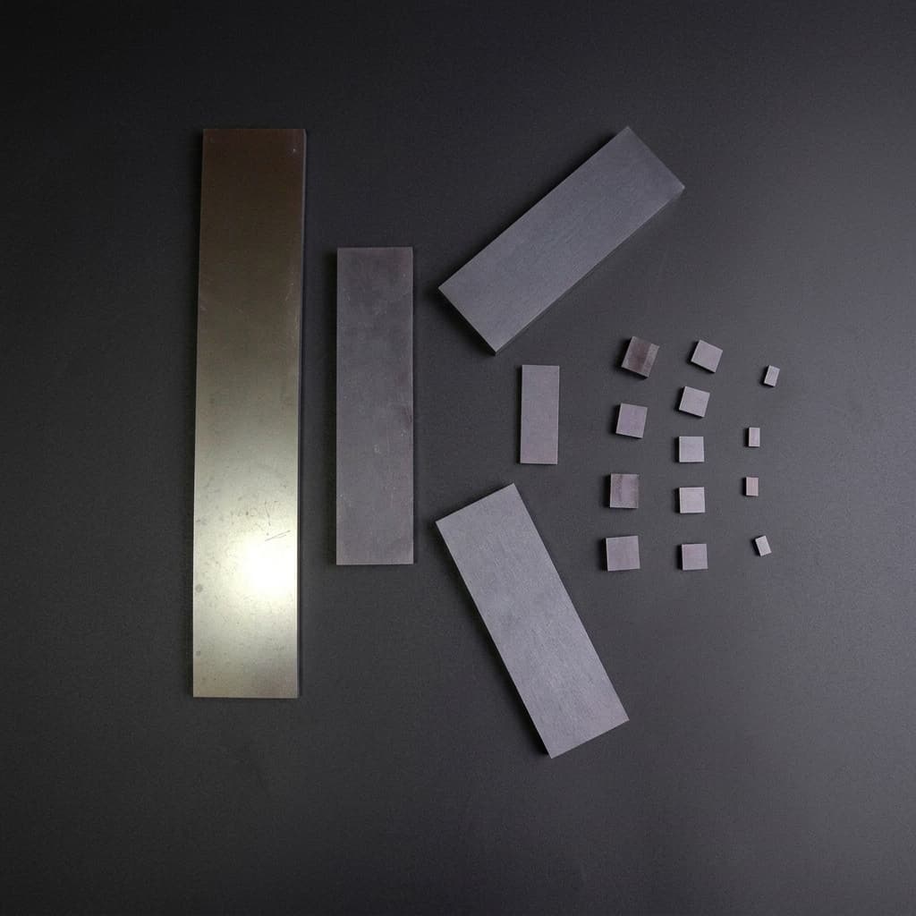
Carbon Graphite Vanes for Dry-Running Rotary Vacuum Pumps and Compressors: Material Grades, Thickness Tolerances, Dew-Point Limits & Sourcing Guide
Compare carbon graphite vanes for dry-running pumps: material grades, thickness tolerances, dew-point risks and wear checks. Send your drawing for RFQ review.
Selection answer: Specify carbon graphite vanes by the exact pump model, approved material grade, dimensional limits, tip orientation, and gas conditions. A matching outline does not establish interchangeability. There is no universal minimum dew point, operating-temperature rating, or discard-height percentage for all carbon vanes; obtain those limits for the named grade and machine.
Published and reviewed: November 7, 2026. This global English-language guide is for maintenance buyers, pump rebuilders, and OEM engineers sourcing vanes for dry-running rotary vacuum pumps and low-pressure compressors. It covers selection and RFQ preparation, not approval for oxygen service, hazardous gases, medical systems, or direct food contact. Those applications require separate equipment and material qualification.
Dry-running rotary vane machines serve printing, packaging, woodworking vacuum tables, and industrial handling systems. Their carbon vanes slide inside rotor slots and contact the cylinder bore without an oil film in the pumping chamber. Oil-free operation describes that lubrication arrangement; it does not itself certify gas purity, particle cleanliness, or freedom from every hydrocarbon contaminant.
A useful purchase specification must connect four things: the material supplier's grade data, the pump manufacturer's fit requirements, the measured gas environment, and an acceptance plan for the delivered set. This guide provides a material screening table, a reproducible clearance calculation, a failure investigation matrix, and a checklist you can copy into an RFQ. The calculations are illustrative engineering checks, not measured pump performance or a substitute for an OEM service manual.
Already have a drawing or a failed sample? Send the pump identity and operating conditions for a vane RFQ review, including what remains unknown, so the quotation can distinguish confirmed requirements from proposed alternatives.
1. Operating Mechanics and Solid Lubrication in Rotary Vane Pumps
To specify the correct carbon-graphite grade, first identify the sliding contact and the gas environment. Both affect wear, even when two vanes have identical dimensions.
Conceptual cross-section: the eccentric rotor changes the volume between adjacent vanes. The transfer layer is exaggerated for visibility; vane count, port position, tip geometry, and clearances vary by machine. On small screens, scroll the diagram horizontally.
Kinematics and Dynamic Loading
An electric motor turns an eccentrically mounted rotor inside a cylindrical bore. Vanes move radially within the rotor slots while maintaining contact with the bore through the machine's designed loading mechanism. The spaces between vanes expand at the inlet, trap gas, then contract toward discharge. Vacuum pumps and compressors use related geometry, but their approved pressure ratios, cooling arrangements, and operating envelopes differ.
The vane must withstand centrifugal loading, gas-pressure loading across its exposed face, and friction during sliding in the slot and along the bore. Motor speed alone is not a material specification: rotor diameter, tip speed, differential pressure, start-stop duty, and contact temperature also matter. Copy those conditions from the equipment documentation rather than inferring them from the motor nameplate alone.
Transfer Film and the Role of the Gas Environment
A graphitic transfer layer can develop on the mating surface during sliding. Its behavior depends on the material pair, surface condition, load, temperature, and environment. Adsorbed species can change graphite friction, so dry-running does not mean that every graphite formulation performs equally in very dry gas.
Lim, Park, and Caron's interfacial-water study discusses earlier graphite dusting observations and examines water-dependent friction using atomic-force microscopy on graphite with metallic tips. Its experimental scale and counterfaces differ from an industrial vane pump. It supports treating environment as a selection variable; it does not establish a pump service-life prediction or an approved dew-point threshold.
Dew-Point Limits: What to Ask Instead of Using a Universal Cutoff
For desiccated air, nitrogen recirculation, or other low-moisture duties, ask the supplier to identify the specific grade qualified for that gas. Do not treat -20°C, -40°C, or another dryer setting as a universal boundary between acceptable and unacceptable carbon vane service. Neither resin impregnation nor metal impregnation alone proves suitability in dry gas.
Record the dew point together with the measurement pressure, sensor location, and temperature. A pressure dew point measured upstream in a compressed line cannot be compared directly with a reading at a lower-pressure pump inlet. Relative humidity without temperature is also insufficient. Distinguish normal operation from startup purge, shutdown, and the driest expected seasonal condition.
The actionable sourcing question is: “What evidence supports this exact grade at our minimum moisture level, gas composition, pressure, temperature, and speed?” If the supplier lacks comparable service evidence, agree a controlled trial with inspection intervals and stop criteria. Do not add humidity, change process gas, or substitute an impregnant without process and equipment approval.
2. Carbon-Graphite Vane Material Classification & Impregnation Chemistry
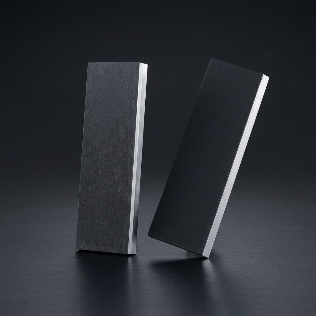
Carbon-graphite materials differ in base carbon, processing, porosity, orientation, and additives. Impregnation can change permeability, strength, and chemical response, but not every suitable vane requires the same treatment. “Carbon graphite” is a material family, not a complete purchase designation.
Material Families and Their Limits
Resin-impregnated materials are candidates for many industrial duties, subject to the resin system, cure, gas exposure, and approved temperature. Higher-temperature resin descriptions must be backed by a named formulation and supplier data. A resin name alone cannot establish continuous service temperature or resistance to solvent vapor.
Metal-impregnated carbons, including antimony- or copper-containing materials, are other mechanical-carbon families to discuss with a supplier. Their use in bearings or seals does not automatically qualify them as vane replacements. Increased density changes centrifugal loading; contact behavior and process contamination also need review. Do not select antimony solely because the gas is dry or the discharge temperature is high.
Proprietary carbon composites may address particular humidity or wear requirements. For example, Schunk's rotary-vane product page describes a named carbon-based material and distinguishes materials offered for lubricated machines. That is evidence for grade-specific selection, not proof that an unrelated supplier's carbon has equivalent properties.
Six-Family Procurement Screening Matrix
This table is a comparison framework, not a catalogue of certified grades or measured property values. Availability and acceptance must be confirmed for the specific vane design.
| Material family | Reason to discuss it | Evidence to request | Selection boundary |
|---|---|---|---|
| Unimpregnated carbon-graphite | A candidate where the pump design and material formulation permit it | Named grade, permeability where relevant, strength and wear evidence | Do not assume all unimpregnated grades leak excessively or all are suitable |
| Resin-impregnated carbon | Review for an existing resin-grade replacement | Exact resin system, operating limits, swelling and compatibility data | A generic “phenolic” label is insufficient |
| Higher-temperature resin grade | Review where the existing material's thermal margin is inadequate | Continuous and transient limits under the actual atmosphere | Do not transfer a short-duration laboratory limit to continuous duty |
| Antimony-impregnated carbon | A supplier-proposed alternative for a defined mechanical duty | Density, strength, contact-pair evidence and process acceptance | Metal content does not establish dry-gas compatibility |
| Copper- or bronze-containing carbon | A supplier-proposed alternative where heat transfer or loading matters | Exact composition, density and vane-specific validation | Added mass and metal transfer require review |
| Proprietary modified carbon composite | Review for unusual humidity, gas, or wear conditions | Traceable grade, test conditions and application evidence | Additive names do not establish purity, regulatory status, or lifetime |
A supplier comparison should list the actual commercial grade, datasheet revision, test direction, temperature conditions, and lot traceability. Do not compare flexural values measured by different methods as if they were interchangeable. ASTM C651-20 identifies a four-point flexural test at room temperature; referencing that method does not certify a vane or establish its hot operating strength. Agree the applicable test edition and acceptance values in the purchase documents.
3. Precision Machining Tolerances, Clearances & Edge Geometries
Vane thickness and slot width jointly determine side clearance. Too little can prevent free movement; too much can contribute to rocking, leakage, and edge damage. There is no capacity-based clearance table that can approve every pump of the same flow rating.
The Three Critical Dimensions
Thickness controls the fit between the sliding faces and the rotor slot. Specify minimum and maximum thickness, parallelism, measurement locations, and reference temperature. Use the OEM drawing or an approved replacement specification. A worn vane gives useful clues, but cannot reveal the original tolerance by itself.
Length is the axial dimension between the end plates. Its tolerance must fit the machine's end-clearance arrangement, including the rotor and plate stack. Do not copy an axial clearance from another pump or assume it equals the difference between vane length and the outside housing length.
Height is the radial dimension governing extension and remaining engagement in the slot. State the new-part height and the OEM minimum permitted height separately. Check how the manufacturer defines its dimensions, because suppliers may use “width” for the radial dimension. A marked sketch avoids ordering a part with length and height reversed.
Worked Thickness-Clearance Calculation
The following is an illustrative room-temperature dimensional example, not a recommended replacement fit. Assume a drawing permits a slot width from 4.000 to 4.018 mm and a vane thickness from 3.965 to 3.975 mm. Calculate total side clearance as slot width minus vane thickness:
- Minimum clearance = 4.000 − 3.975 = 0.025 mm.
- Maximum clearance = 4.018 − 3.965 = 0.053 mm.
The maximum uses the widest slot and thinnest vane. Using nominal sizes or combining the wrong extremes understates the tolerance stack. This calculation provides total clearance between both faces, not clearance per side. It excludes distortion, contamination, thermal growth, moisture response, and measurement uncertainty, so it cannot establish clearance throughout the operating-temperature envelope.
If a drawing uses ISO fit designations, verify the relevant nominal-size band and limit deviations rather than relabeling a bilateral ground thickness as “h7.” For example, a 3.970 ±0.005 mm vane is an explicit size range; it is not automatically a standard h7 vane on a 4.000 mm basic size.
Dimensional Acceptance Checklist
| Feature | Define before ordering | Verify at incoming inspection |
|---|---|---|
| Thickness | Lower and upper limits; temperature; measurement locations | Measure multiple positions with suitable calibrated equipment |
| Face parallelism | Drawing tolerance and datum scheme | Compare thickness across both sliding faces |
| Axial length | Limits and approved total end clearance | Compare with drawing and the machine's assembled stack |
| Radial height | New-part size and separate discard limit | Record height at the OEM-defined inspection points |
| Tip profile | Radius or bevel, reference face, and rotation arrow | Compare against the approved profile and installation diagram |
| Edge condition | Approved chamfers or edge breaks | Inspect for chips and handling damage without changing the profile |
| Surface finish | Required faces, roughness parameter, and acceptance method | Use the agreed method rather than visual shine alone |
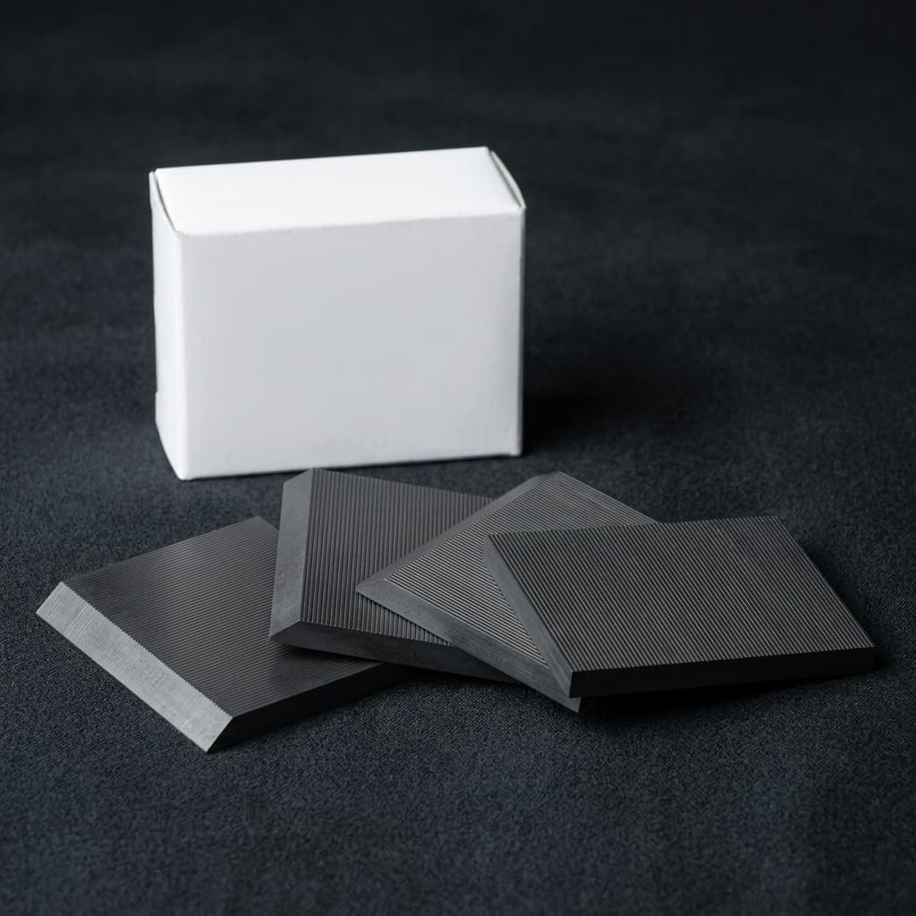
Bevel Angles and Tip Profiling
Vane tips may be beveled, radiused, or otherwise profiled. Slot angle and direction of rotation affect how that profile contacts the bore. Preserve the reference-face marking and use the OEM installation drawing; “bevel forward” is ambiguous without a viewing direction. Do not reverse a profiled vane or hand-chamfer its contact edge to make it appear to fit.
A pre-profiled tip still requires the manufacturer's startup procedure. It does not guarantee immediate full pumping performance or eliminate inspection after the first run. For uncertain replacement geometry, resolve the drawing before ordering a production batch.
4. Anisotropic Grain Orientation and Bending Strength
Manufacturing route can make carbon properties direction-dependent. Where the supplier identifies an anisotropic grade, request a stock-orientation sketch linked to the finished vane drawing and strength results measured in the relevant direction. “Fine grain” and “isotropic” should be supported by the grade specification, rather than inferred from a photograph.
Do not impose a universal rule that grain must always run parallel to one vane dimension. Loading, base material, stock orientation, and machining route must be considered together. Isostatically produced stock can be a candidate for more uniform properties, but its process name alone does not establish finished-vane strength or freedom from machining damage.
For a new material or supplier, approve a first article before repeat production. Record dimensions, edge condition, orientation where relevant, and the agreed material identification. A density or hardness match alone cannot prove equivalent wear behavior. Prepare the drawing and material questions for review before treating a sample as an approved substitute.
5. Wear Limits, Replacement Thresholds & Failure Analysis
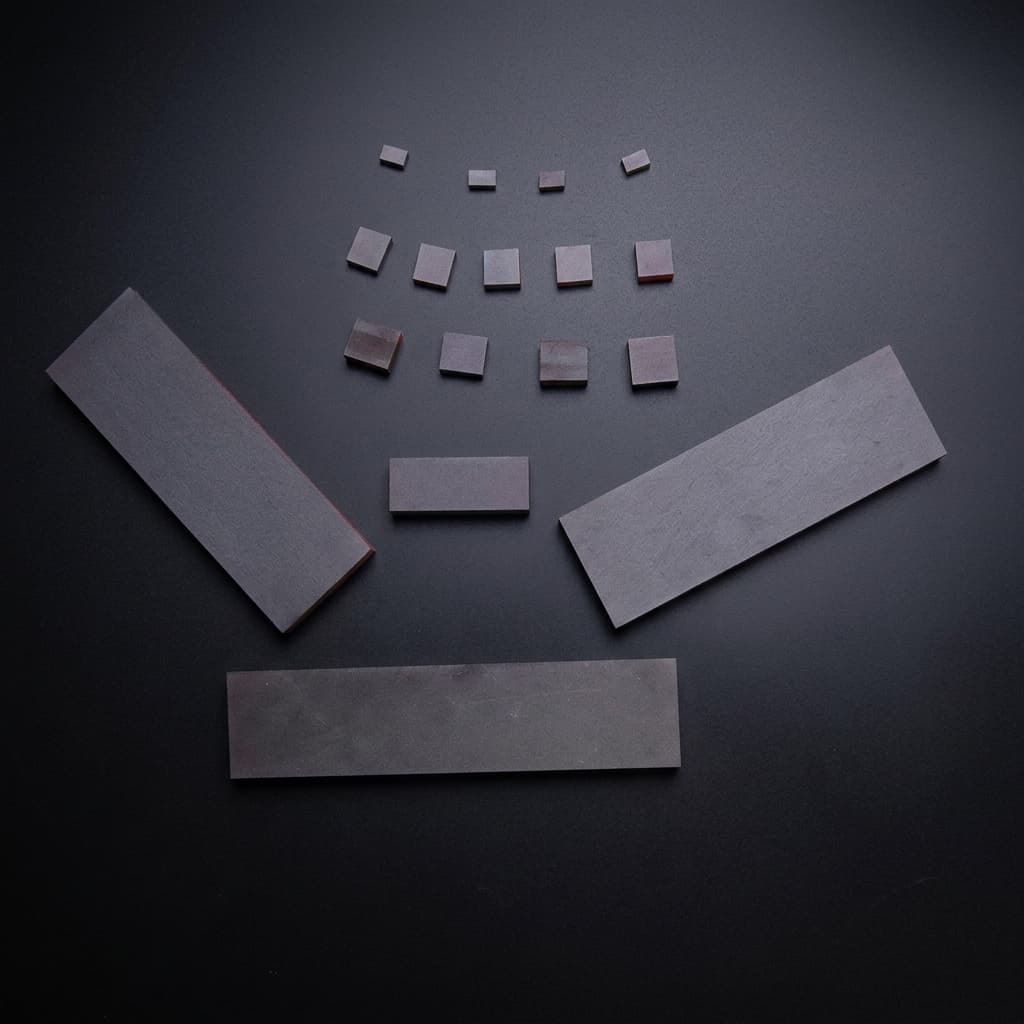
Carbon vanes are wear components. Their remaining radial height affects how much material stays engaged in the rotor slot at maximum extension. Running below the approved limit can increase the risk of fracture and internal damage, even if the pump still produces useful vacuum.
Use the Model-Specific Discard Height
Do not apply a universal 25%–35% wear allowance. Obtain the minimum vane height and inspection procedure for the exact pump model, revision, and installed vane kit. If those are unavailable, mark the replacement decision unresolved and contact the equipment manufacturer or an authorized service specialist. Do not derive a safe limit from an unrelated model or a used part offered online.
At each planned inspection, follow the OEM isolation and cool-down procedure, record running hours and operating conditions, and measure every vane at the prescribed positions. Compare the smallest permitted measurement with the manual's limit. Note chips, cracks, sticking, and uneven wear as separate rejection conditions; average height cannot compensate for a damaged blade.
A useful wear record includes the installed grade, batch, initial height, measured minimum height, inspection date, operating hours, and any change in gas conditions or filters. Trend that record to plan the next inspection within the OEM interval. Do not linearly extrapolate one early measurement into a guaranteed service life: running-in and changed duty can alter the wear rate.
Replace a set according to the OEM service instructions. Where matched-set replacement is specified, keep the supplied set together and investigate why a single vane failed. Replacing the broken piece without finding debris, slot damage, or an operating upset leaves the initiating problem unresolved.
Troubleshooting Matrix: Six Failure Patterns
These are investigation paths, not unique diagnoses or instructions to modify the machine. Several causes can produce the same appearance.
| Failure appearance | Possible contributors | Evidence to collect | Next decision |
|---|---|---|---|
| Chipped or scalloped tip | Profile orientation, damaged bore, debris, excess movement | Photos, rotation direction, tip drawing and slot measurements | Resolve geometry or damage before installing a new set |
| Fracture near the slot lip | Insufficient remaining height, abnormal load, impact or material damage | Minimum height, OEM wear limit and event history | Investigate the load and support condition |
| Rapid powder generation | Unsuitable gas environment, contamination or counterface condition | Dew point with measurement pressure, gas analysis and wear trend | Review the specific grade and operating conditions |
| Vane sticking in a slot | Lost clearance, deposits, distortion or material response | Cold dimensions, deposits and operating temperatures | Compare with OEM fit limits; do not simply enlarge the slot |
| Blistering or surface damage | Thermal exposure or chemical incompatibility | Contact/discharge temperature history and gas composition | Check cooling, restrictions and the named material's limits |
| Uneven axial-end wear | End-clearance problem, alignment or bearing condition | Assembly measurements and service history | Have the end-clearance and alignment arrangement checked |
Do not hone the cylinder, grind a slot wider, or change shims from a generic troubleshooting table. Such work changes the machine's fit and can conceal the original fault. Use the manufacturer's service dimensions and an approved repair process.
6. Sourcing & RFQ Engineering Checklist
Use this checklist to compare quotations on the same basis. Unknown fields should remain visibly unresolved rather than being replaced with generic catalogue values.
- 1. Equipment identity: Manufacturer, complete model, serial/revision, vane kit number, and whether the RFQ is for a replacement or new OEM design.
- 2. Operating duty: Gas composition, contaminants, inlet and discharge pressure with absolute/gauge basis, speed, temperature locations, and continuous or cyclic duty.
- 3. Moisture conditions: Minimum and normal dew point, measurement pressure and sensor location, plus purge and shutdown conditions.
- 4. Drawing limits: Length, radial height, thickness, datums, parallelism, surface finish, and approved slot and end clearances. Label dimensions on a sketch.
- 5. Tip geometry: Bevel/radius, reference face, rotation arrow, and OEM installation orientation.
- 6. Material identity: Actual supplier grade and revision, impregnant/additives, required evidence, and whether substitution requires written approval.
- 7. Inspection and traceability: Lot identification, material report, dimensional results, sampling plan, and agreement on test methods and acceptance values.
- 8. Set requirements: Correct vane count, complete-set packaging, and any mass-matching requirement stated by the machine designer. Do not invent a universal weight tolerance.
- 9. Cleanliness and handling: Approved cleaning process, chip protection, storage instructions, and any restriction on oil, solvents, packaging residue, or contamination.
- 10. Commercial and trial plan: Quantity, repeat forecast, destination, first-article approval, lead time, documentation, and a defined trial/inspection plan for an alternative grade.
Separate quotation acceptance from engineering release. A supplier may be able to machine the shape while grade compatibility or the OEM wear limit remains unresolved. Release repeat orders only against the approved drawing, material designation, and first-article record. This keeps price comparisons from quietly comparing different technical requirements.
7. Frequently Asked Questions (FAQ)
Can I run carbon graphite vanes in an oil-lubricated pump?
Use the material and vane kit approved for that lubricated machine. A dry-running vane is not automatically interchangeable. Lubricant compatibility, swelling, slot behavior, and tip design need confirmation; neither “all graphite is suitable” nor “all lubricated pumps use fiber vanes” is a reliable selection rule.
Why might all vanes need replacement together?
The OEM may specify replacement as a complete matched set to control dimensions and material consistency. Follow that instruction and inspect the machine after any fracture. A new individual vane does not correct an existing slot, bore, contamination, or operating-condition problem.
Does dry nitrogen automatically require antimony-impregnated vanes?
No. Request a grade qualified for the actual gas moisture level, pressure, temperature, and loading. An antimony description does not establish humidity-independent lubrication. A proposed substitute needs evidence relevant to the vane duty and a controlled validation plan if equivalence is unproven.
What service life should I put in a purchasing specification?
Start with the OEM inspection schedule and your documented wear history under comparable duty. Agree how hours, remaining height, and reject conditions will be recorded. A blanket hours claim without gas, speed, load, filtration, and wear-limit context is not a dependable acceptance criterion.
What surface finish is required on the cylinder wall?
Use the equipment manufacturer's bore specification and repair limits. Roughness, waviness, scoring, material, and geometry all affect the sliding pair. A single generic Ra value cannot approve a damaged bore, and polishing or honing without the repair specification can change the fit.
How should carbon vanes be stored?
Keep complete sets in the supplier's protective packaging, supported against bending and edge impacts, and protected from contamination and temperature extremes. Follow the named grade's storage and conditioning instructions, especially where humidity response matters. Inspect packaging and brittle edges before installation.
Can worn vanes be re-ground for another pump?
Do not assume that resizing creates a usable replacement. It changes the available height, tip geometry, thickness allowance, and possibly orientation or surface condition. Use new parts to an approved drawing unless the equipment manufacturer has an explicit rework procedure for that application.
Are carbon graphite vanes automatically food-contact or medical compliant?
No. Identify whether the vane contacts the product or only a separate process-gas stream, and obtain the applicable material and equipment documentation for the destination market. A resin family, “oil-free” label, or general supplier statement does not establish compliance for a finished part or system.
8. Sourcing Custom & OEM Carbon Vanes from Custom Graphite Parts
Use our carbon graphite wear parts catalogue to begin a discussion about custom dimensions, sliding conditions, and material selection. The related carbon graphite bearings and bushings page covers other mechanical-carbon applications; it does not establish interchangeable grades for pump vanes.
For a quotation, send the approved drawing or a clearly labeled sample, equipment identity, operating conditions, set quantity, and destination. Identify any unresolved material, tolerance, or compliance requirement. A worn sample can support measurement, but cannot by itself establish the original grade, nominal dimensions, or safe discard height. Brand and model references in this guide identify equipment only; they do not imply OEM endorsement or approved replacement status.
Ask the quotation to state the proposed grade, achievable drawing limits, inspection deliverables, packaging, and first-article requirements. Any material substitution or unverified fit should be resolved before production approval. Specific machining tolerances, certificates, lead times, and testing are subject to review of the actual request.
Sources & References
Sources checked November 7, 2026. These references support material-selection principles and test-method identification. They do not certify our products or supply model-specific dimensions, discard limits, or guaranteed service life. Obtain those from the exact machine manual and the proposed material supplier.
- Schunk Carbon Technology — Rotary Vanes. Manufacturer information on a named carbon-based vane material and application-specific selection; not a universal property table.
- Lim, Y.; Park, H.; Caron, A. (2019) — Investigation on the role of interfacial water on the tribology between graphite and metals. RSC Advances, 9, 7285–7291. Original atomic-scale research; its test conditions must not be converted into an industrial pump dew-point limit.
- ASTM International — C651-20: Four-point flexural strength testing of manufactured carbon and graphite at room temperature. Standard catalogue record; agree the required edition and acceptance criteria. A test-method reference is not a product certificate.
Author

Graphite CNC machining, EDM electrode, mold tooling, and export-aware sourcing specialists.
More Posts
Graphite Heating Elements for Vacuum Furnaces: Design and Maintenance Guide
Learn how to optimize the lifespan of your vacuum furnace graphite hot zone. We cover heating element design, oxidation prevention, and when to choose molded over isostatic graphite.
Continuous Casting Graphite Dies: Grain Selection, Bore Tolerances, Freeze-Line Control & Alloy Wear Life Guide
Compare continuous casting graphite dies for copper, brass and bronze. Check grain data, bore tolerances, freeze-line risks and wear-life trials for your RFQ.
Isostatic vs. Molded Graphite: Which Grade Should You Choose?
An engineering guide comparing isostatic and molded graphite. Learn about grain size, density, strength, and how to select the right graphite grade for EDM, continuous casting, and vacuum furnaces.