
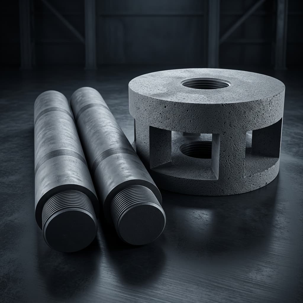
Graphite Rotors and Shafts for Aluminum Degassing: Wear Resistance and Lifespan Optimization
A comprehensive engineering and procurement guide to extending the lifespan of graphite degassing rotors in aluminum foundries. Learn about high-temperature oxidation, anti-oxidation coatings, material selection, and operational best practices.
Decision-Level Conclusion: In modern aluminum casting, the efficiency of hydrogen and inclusion removal relies entirely on the rotary degassing process. However, graphite rotors and shafts remain the primary consumable bottleneck due to rapid oxidation and mechanical erosion at 700°C–800°C. For foundry procurement teams and process engineers, transitioning from untreated standard graphite to high-density, anti-oxidation coated isostatic graphite rotors represents the single highest-ROI improvement available. Proper material selection combined with strict preheating and rotational speed controls can extend rotor lifespan by up to 300%, drastically reducing downtime and lowering the cost per cast.
For foundries producing high-quality aluminum alloys—whether for automotive structural components, aerospace parts, or premium extrusions—removing dissolved hydrogen gas and non-metallic inclusions from the molten melt is non-negotiable. The industry standard for this process is rotary degassing, which utilizes a specialized graphite rotor and shaft assembly to inject inert gas (typically Argon or Nitrogen) into the molten aluminum.
While graphite is chosen for its excellent thermal shock resistance, non-wettability with molten aluminum, and chemical inertness, it is not immune to degradation. In fact, the harsh environment of an aluminum holding furnace or degassing ladle pushes graphite to its absolute limits. This comprehensive guide breaks down the mechanisms of rotor failure, compares advanced surface treatments, and provides an actionable framework for procurement teams and engineers to optimize their graphite rotor sourcing strategy.
1. The Anatomy of Rotor Failure: Why Do Graphite Degassing Shafts Break?
To optimize the lifespan of a graphite rotor, engineers must first understand exactly how and why it degrades. Graphite does not melt in an aluminum furnace; rather, it degrades through a combination of chemical, mechanical, and thermal forces.
High-Temperature Oxidation (The Silent Killer)
The most significant enemy of any graphite component in an oxygen-rich environment is oxidation. Pure carbon begins to oxidize rapidly when exposed to atmospheric oxygen at temperatures exceeding 500°C (932°F). In a typical aluminum degassing operation, the molten metal sits at 700°C to 800°C. While the portion of the rotor submerged in the melt is somewhat protected from oxygen (as it is surrounded by liquid aluminum), the portion of the shaft located at the "waterline"—the boundary between the molten metal surface and the ambient air—is exposed to the absolute worst conditions. It experiences both extreme heat and full atmospheric oxygen exposure. This localized oxidation causes the graphite shaft to thin out rapidly at the liquid line, eventually leading to structural failure where the shaft simply snaps off under the torque of the drive motor.
Mechanical Erosion and Abrasion
As the rotor spins at speeds of 300 to 600 RPM, it acts as a mechanical pump, shearing the inert gas bubbles to maximize surface area for hydrogen absorption. However, molten aluminum alloys, especially those containing high silicon (like A356) or undissolved dross particles, act as a highly abrasive slurry. Over time, the sharp geometries of the rotor head—the flutes, gas dispersion holes, and mixing vanes—are worn down. As the geometry degrades, the rotor's ability to shear gas bubbles decreases. The bubbles become larger, meaning less surface area for hydrogen diffusion, which ultimately leads to poor degassing efficiency and high porosity in the final cast parts.
Thermal Shock and Structural Stress
Although graphite boasts exceptional resistance to thermal shock compared to ceramics, throwing a room-temperature rotor directly into an 800°C bath of molten aluminum induces immense internal stress. Micro-fractures can develop within the graphite matrix. If liquid aluminum penetrates these micro-fractures during operation, the subsequent cooling phase (when the rotor is removed) causes the trapped aluminum to solidify and expand, cracking the rotor head from the inside out.
2. The Foundation: Selecting the Right Graphite Grade
Not all graphite is created equal. The raw material grade chosen by your machining partner dictates the baseline performance of your rotor assembly before any surface treatments are even applied.
For continuous and heavy-duty aluminum degassing, extruded graphite or coarse-grain molded graphite should be strictly avoided. These grades have high porosity (often exceeding 15%), large grain sizes, and lower mechanical strength. High porosity means that molten aluminum and oxygen can easily penetrate deep into the material's matrix, causing rapid internal degradation.
The industry best practice is to specify high-density Isostatic Graphite. Isostatic pressing ensures that the graphite possesses an extremely uniform, isotropic structure with a fine grain size (typically 10-15 microns or less).
- Higher Density (≥ 1.80 g/cm³): Leaves less open porosity for oxidation to penetrate.
- Higher Flexural Strength: Reduces the risk of the shaft snapping under high-torque motor loads or accidental mechanical impacts during handling.
- Precision Machinability: Isostatic graphite can be machined to incredibly tight tolerances, ensuring perfect concentricity. A rotor shaft that lacks concentricity will wobble at 400 RPM, causing severe vibration that damages the degassing machine's bearings and accelerates mechanical wear on the rotor itself.
3. Surface Treatments: The ROI Multipliers
While high-density isostatic graphite is excellent, it is still naked carbon that will oxidize at 800°C. To achieve commercially viable lifespans—often extending the usable life from 15 days to over 60 days—specialized surface treatments are necessary.
Procurement teams must carefully evaluate the ROI of these treatments. While treated rotors carry a higher upfront unit cost, the reduction in downtime, labor (for rotor swaps), and catastrophic failures makes them dramatically cheaper over a quarter's production.
| Treatment Type | Mechanism of Action | Oxidation Resistance (700°C+) | Mechanical Abrasion Resistance | Relative Lifespan Multiplier | Best Application Scenario |
|---|---|---|---|---|---|
| Standard Untreated | None. Raw machined graphite. | Poor (Oxidizes rapidly) | Moderate | 1.0x (Baseline) | Short-run prototyping, low-temp zinc casting. Not recommended for Al. |
| Resin Impregnation | Fills open pores with high-temp phenolic resins to block gas entry. | Fair to Good | Moderate | 1.5x - 2.0x | Budget-conscious foundries with easily accessible degassing stations. |
| Phosphate Salt Impregnation | Deep pore penetration with inorganic anti-oxidation salts. | Good | Good (Hardens surface) | 2.5x - 3.0x | Standard aluminum die casting operations. Excellent cost-to-performance ratio. |
| Ceramic Coating (SiC / Al2O3) | Applies a physical ceramic barrier over the entire shaft and rotor. | Excellent | Excellent | 3.5x - 5.0x | Aggressive alloys, highly abrasive melts, operations demanding maximum uptime. |
| Proprietary Nano-Coating | Multi-layer approach: inner salt impregnation + outer ceramic nano-seal. | Supreme | Excellent | 5.0x+ | High-purity aerospace aluminum, 24/7 continuous casting operations. |
| Sleeve Protection (Alumina) | Sliding a physical ceramic sleeve over the "waterline" of the shaft. | Excellent at the waterline | N/A (shaft only) | Variable | Used in conjunction with treated rotors for ultimate shaft protection. |
Note: Lifespan multipliers are estimates based on standard A356 aluminum melts operating at 740°C with optimal preheating protocols.
4. Operational Best Practices: Don't Kill Your Rotors
Even the most expensive, proprietary-coated graphite rotor can be destroyed in a matter of days if operational protocols are ignored. Foundry personnel must treat degassing rotors as precision engineering consumables, not indestructible crowbars.
1. Mandatory Preheating
Never insert a cold graphite rotor into molten aluminum. The sudden 700-degree temperature jump will cause severe thermal shock, leading to invisible micro-cracks that compromise the structural integrity of the head.
- Protocol: Suspend the rotor 5 to 10 inches above the molten metal surface for at least 15 to 30 minutes before insertion. This allows ambient radiant heat to slowly bring the graphite up to 300°C - 400°C.
2. Rotational Speed Optimization
More RPM does not automatically mean better degassing. Running a rotor at maximum speed creates a deep vortex on the surface of the melt. This vortex actively sucks atmospheric oxygen and floating surface dross directly down into the melt, defeating the purpose of degassing and severely abrading the rotor head.
- Protocol: Operate at the minimum RPM required to achieve a rolling, bubbling surface without breaking the surface tension or forming a visible vortex. Typically, this falls between 250 and 450 RPM, depending on the baffle design and ladle geometry.
3. Maintain Continuous Gas Flow
Never submerge the rotor without the inert gas already flowing, and never turn off the gas while the rotor is still submerged.
- Protocol: If the rotor enters the melt without positive gas pressure, molten aluminum will immediately rush into the gas dispersion holes and flutes. When the metal solidifies, it will permanently plug the rotor, rendering it useless. Always maintain a baseline flow of argon or nitrogen during the entire submersion cycle.
4. Gentle Cleaning
After removal from the melt, some aluminum may stick to the rotor.
- Protocol: Do not strike the rotor with a steel hammer to knock off dross. Gently scrape off excess aluminum with a soft tool while the rotor is still hot. Banging the rotor will crack the anti-oxidation coating, exposing the naked carbon beneath and guaranteeing premature failure on the next run.
5. Procurement Engineering: The Sourcing Checklist
When qualifying a new supplier for custom graphite degassing rotors, procurement teams and supplier quality engineers (SQEs) must look past the price tag and audit the supplier's technical capabilities. Use this checklist when requesting quotes:
- Material Certification: Does the supplier provide a Certificate of Analysis (CoA) proving the use of isostatic graphite with a density of at least 1.80 g/cm³ and a maximum particle size of 15μm?
- Concentricity Tolerances: Can the supplier guarantee shaft straightness and concentricity to prevent high-speed wobble? Ask for their standard CMM inspection reports.
- Thread Precision: The connection between the shaft and the rotor head relies on coarse graphite threads. Are these threads CNC milled to prevent loosening and gas leakage, or are they manually tapped?
- Coating Transparency: What specific anti-oxidation treatment is being applied? Avoid suppliers who claim "magic" coatings without explaining if it is an impregnation, a wash, or a baked ceramic layer.
- Custom Geometry Capability: Can the supplier reliably reverse-engineer your existing OEM rotor geometries (flutes, impellers) and provide CAD verification before production?
6. Frequently Asked Questions (FAQ)
What is the typical lifespan of a graphite degassing rotor?
Under optimal conditions in standard aluminum alloys, an untreated rotor may last 1 to 2 weeks. A high-quality, anti-oxidation coated isostatic graphite rotor should consistently last 4 to 8 weeks, depending on the number of degassing cycles per day and the aggressiveness of the alloy.
Should we use Argon or Nitrogen for degassing?
Both are effective. Argon is heavier, completely inert, and generally provides better degassing efficiency, but it is significantly more expensive. Nitrogen is cheaper and widely used, but it can react slightly with aluminum at very high temperatures to form dross (aluminum nitride). The choice depends on your local gas costs and strictness of alloy purity requirements.
Can a broken rotor head be repaired?
No. Once a graphite rotor head cracks or degrades past its functional geometry, it must be replaced. However, if the shaft is still in excellent condition and features a threaded connection, you can simply unscrew the broken head and attach a new one, saving money on shaft replacement.
Why does our rotor shaft always break exactly at the surface of the melt?
This is the classic symptom of severe localized oxidation. The waterline is where atmospheric oxygen and high heat meet. To fix this, you must switch to an anti-oxidation coated shaft or install a physical ceramic protection sleeve over the exposed portion of the shaft.
Conclusion & Next Steps
Accepting frequent rotor replacements as a "cost of doing business" is an outdated mindset. By transitioning to high-density isostatic graphite, mandating anti-oxidation treatments, and enforcing strict preheating protocols on the foundry floor, you can drastically reduce downtime and consumable costs.
Are your current rotors failing prematurely? It might be time for a material audit.
At our facility, we specialize in CNC-machining custom graphite degassing rotors and shafts to your exact dimensional specifications. We utilize premium, ultra-fine isostatic graphite and apply proprietary deep-penetration anti-oxidation treatments designed specifically for aggressive aluminum foundries.
Contact our engineering team today to request a quote, share your current rotor CAD files, or discuss a trial run of our high-lifespan treated assemblies. Let's engineer a solution that keeps your production running longer.
Sources & References
- Foseco Foundry Practice - Degassing of Aluminum Alloys and Rotor Efficiency. Foseco Non-Ferrous Solutions.
- Journal of Materials Processing Technology - Oxidation mechanisms of carbon-graphite materials at high temperatures (500°C+). Available via ResearchGate.
- Industry Best Practices for Surface Treatments in Non-Ferrous Foundries. Data on lifespan multipliers and impregnation vs. coating wear resistance provided by SF-Foundry Consumables.
Author

Graphite CNC machining, EDM electrode, mold tooling, and export-aware sourcing specialists.
Categories
More Posts
Isostatic vs. Molded Graphite: Which Grade Should You Choose?
An engineering guide comparing isostatic and molded graphite. Learn about grain size, density, strength, and how to select the right graphite grade for EDM, continuous casting, and vacuum furnaces.
Graphite CNC Machining Design Guide: Tolerances, Threads, and Cost Drivers
Designing custom graphite parts? Read our CNC machining guide covering standard tolerances, threading considerations, wall thickness limits, and tips to reduce your manufacturing costs.
Carbon-Carbon (C/C) Composites vs. Isostatic Graphite: Vacuum Furnace Fixture Selection Guide
Compare C/C composites vs isostatic graphite for vacuum furnace fixtures: thermal mass, TCO, risks, checklist, and RFQ guidance from Custom Graphite Parts.